Included valve angles have been in F1 for over 50 years and compound angles since the 90s. Not exactly unknown territory either.
It also makes sense why they wouldn't implement this on the MCL-32 the taller head might have needed chassis modification, at the very least a redesigned air-box, and the exhaust manifolds would also change.roon wrote: ↑08 Feb 2018, 20:48All the photos I've seen suggest close camshaft spacing, which may imply what you're implying.godlameroso wrote: ↑08 Feb 2018, 05:53What if using a pent roof combustion chamber isn't the best solution? But you arrive at this conclusion because you can't accurately model the type of combustion chamber geometry you want to use? Or that it's taking too long in order to learn and implement knowledge. But what if you design a cylinder head that uses a very flat valve angle, which is easier to model, true you sacrifice some efficiency, but it's easier to develop. You evolve your models, you try them with new combustion chamber designs. Eventually you learn enough that your meshes are fine enough and your simulations are so good that you can predict and develop with more complex combustion chamber shapes.
Would in part explain a tall cylinder head.![]()
4-6 weeks.
Engineers haven't been doing CFD LES modeling for that long, and the difference between today and 2004 is on another level. On top of that F1 engineers haven't been doing this type of lean burn combustion for 50 years, the power units are only 4 years old. Developing good correlation takes times, it takes a lot of time to develop the meshes for complex port and valve geometries. A lot easier to get good correlation with relatively low computing power by using completely vertical valves and not using too complex combustion chamber shapes.
What I'm saying is: tightly coupled camshafts may mean valves parallel to, or near parallel to, cylinder centerline. If we assume direct action buckets. Camshaft center spacing can be extracted from photos by using the known dimensions of the M12 mounting holes.
They are using finger followers - it's pretty much the only sensible solution with compound angles.
Wazari wrote: ↑Mudflap wrote: ↑08 Feb 2018, 23:21I'm not sure what your sources are but they are wrong. A good mesh is something you do in an afternoon and I speak from experience.
Sure it does take a while to calibrate your models but once you have an instrumented single cylinder running it is quite straightforward.
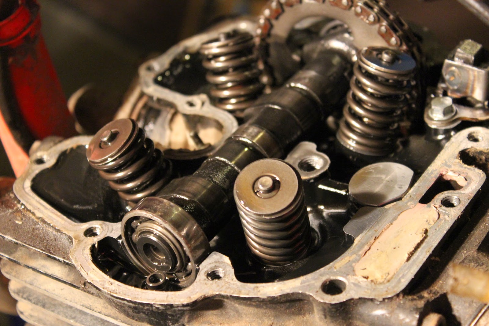
Suggesting to use vertical valves for the sake of simplicity is really silly.
Also I don't really know of anyone using in house CFD in F1.
They might start using diesel pistons when they will be allowed to use diesel as fuel.


I wouldnt go by what Wazari says, his parables are so deep he himself sometime forgets what he wanted to convey.godlameroso wrote: ↑08 Feb 2018, 23:37[quote=Mudflap post_id=737039
Wazari wrote: ↑
FW17 wrote:
Hi Wazari
Are there any methods of flame quenching away from piston crown and cylinder walls currently being used in F1
What are the likely ways of achieving this?
1. I think I would assume so.
2. Various methods. 
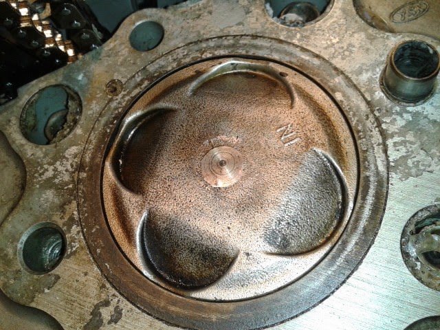
CC design or lack of CC as we conventionally know it, piston groves, diagonal piston ports, slots, etc.
Just mulling over this, that's all. I could be way off, sure good meshes can be done in a day, but have them be as accurate with complex shapes and that afternoon can turn into a few months.
And I'm not talking about the thermodynamics that's child's play. I'm talking about the fuel reaction chemistry side of it. You can't develop your process if you can't see how your process influences the reactions. The 50hp gain from Mercedes wasn't just some exotic fuel blend, but understanding and being able to take advantage of the way the fuel combusts.
If you can model how fuel combusts more accurately than the next guy, you can run it closer to the edge of detonation.