Scarbs T-Tray proposal

Here are our CFD links and discussions about aerodynamics, suspension, driver safety and tyres. Please stick to F1 on this forum.
User avatar
ringo
230
Joined: 29 Mar 2009, 10:57

Re: Scarbs T-Tray proposal

Post

hardingfv32 wrote:Why are you talking about bodies? Is the body from the floor section up? The RB has a separate floor assembly. Can it not bend without influencing the body? How could the body be affected?

Can an interior section of the floor assembly bend without the perimeter of the floor assembly being effected, say 5-6mm?

To be very precise, we are only concern about the movement of the plank as the is the only part check for wear.

I do not understand your concerns. Can you clarify?

Brian
If you put a balloon against your forehead, then let someone kick it. How far would your head kickback? Chances are the balloon distorts and your head doesn't move. Compare this to putting a bowling ball against your forehead. I know the bowling wont compress but your head will the the thing that moves.
The difference is between the stiffness of the bowling ball and the balloon.
It doesn't matter if you are only interested in one part of the system. The external forces have to be understood and resolved before you move on to the internal stuff.

So for a rough example if the car weighs 6400N and has about 12800N of downforce, a total weight of 19.2 kN over the axles at an instant, as the splitter contacts the ground it will be supporting a fraction of this weight, let's say less than a third, as the wheels are supporting the rest.
The stiffness of the floor and the plank have to be at a level where this force can deflect it if it is that it must bend and be flush with the track. If it takes more than this reaction force to deflect the splitter, the whole car body will simply move as one piece and the splitter simply wont move.
The balloon and bowling ball analogy is a good reference of what i am getting at here. Pardon me if i can't make it clear enough.

So how weak do we need to make the splitter joint so that it can bend under say a third of the load on the axles.. 6.4kN from my example?
For Sure!!

User avatar
horse
6
Joined: 23 Oct 2009, 17:53
Location: Bilbao, ES

Re: Scarbs T-Tray proposal

Post

Image

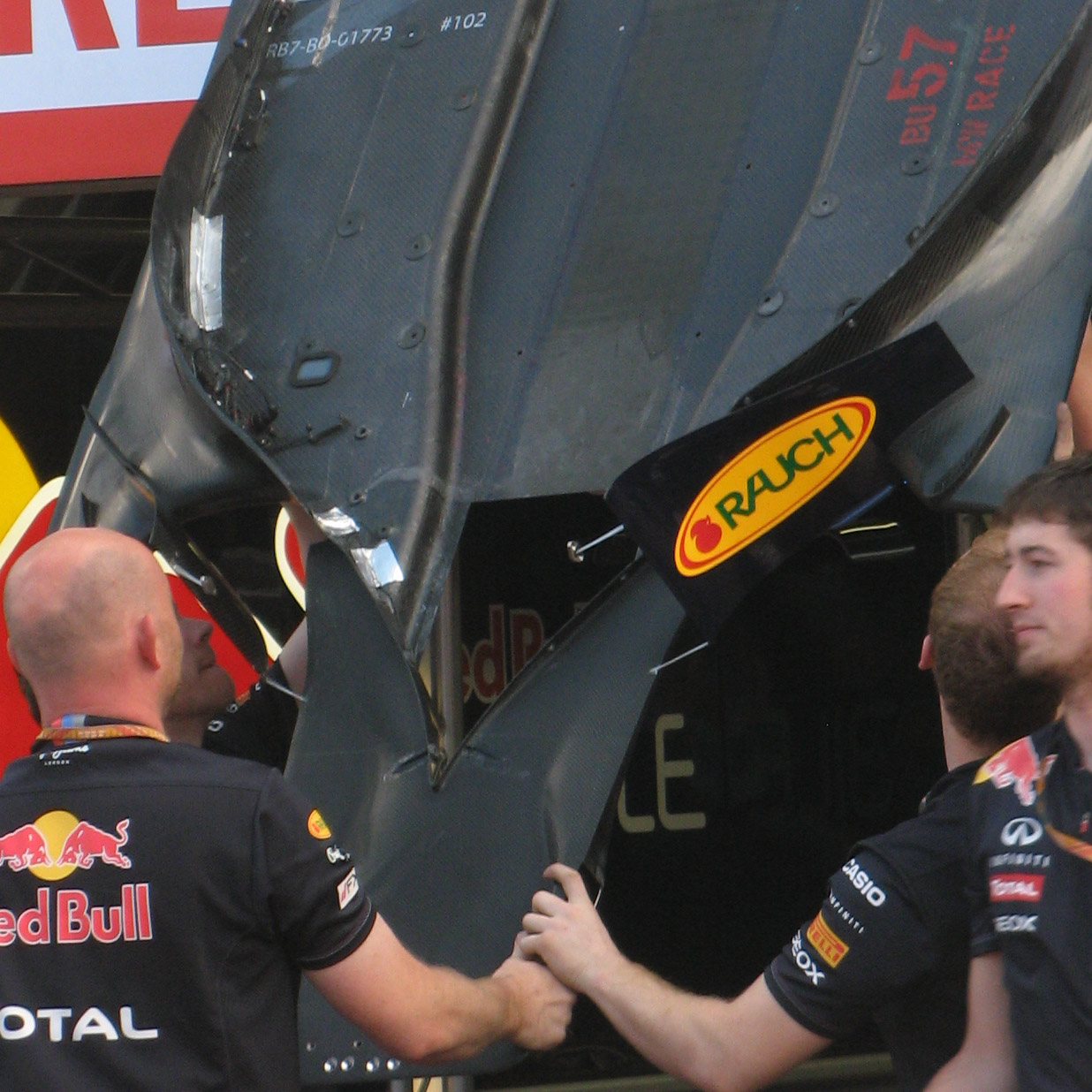
So say the t-tray was pivoted at the V seen in this picture, then the "flaps" of the t-tray behind the V will move up and down the chassis depending on whether the t-tray is in contact with the ground or not.

One question that springs to mind is whether it's legal to have this gap between the t-tray and the chassis? Those flaps can't be secured to the chassis or the pivot would not move.

The second thing here is that the barge board are connected to those flaps on the t-tray. So if that part of the t-tray is moving down then so are the barge boards. Is such movement desirable?
"Words are for meaning: when you've got the meaning, you can forget the words." - Chuang Tzu

hardingfv32
hardingfv32
35
Joined: 03 Apr 2011, 19:42

Re: Scarbs T-Tray proposal

Post

Ringo

I just tested a 8.3 mm thick, 300 mm square of cabinet grade plywood. Resting on the outer edges and and force applied along the center axis. It measures 30 kg for a 5 mm deflection. Say we assume a force of 40 kg for a 10 mm thick piece of ply.

I am going to assume that system requires 200 kg of strength to pass the current test, so i would estimate 240 kg would move a system like we are talking 5 mm. This is a rough estimate as I do not know how the plank in mounted. I am assuming there is NO composite floor to deal with, as illustrated by RB's floor section.

You still have not described what you include in your definition of "body". I do not think anything above the floor section (RB example) has any relevance.

Brian

hardingfv32
hardingfv32
35
Joined: 03 Apr 2011, 19:42

Re: Scarbs T-Tray proposal

Post

"One question that springs to mind is whether it's legal to have this gap between the t-tray and the chassis? Those flaps can't be secured to the chassis or the pivot would not move."

That portion of the t-tray behind the fulcrum only has to move downward for this system to work. At rest it could be in contact with the chassis, just not attached.

"One question that springs to mind is whether it's legal to have this gap between the t-tray and the chassis? Those flaps can't be secured to the chassis or the pivot would not move."

Remember this is a system designed to reduce plank wear from occasional contact with the track surface. Any dimensional change to the barge boards would be brief.

Brian

User avatar
PlatinumZealot
559
Joined: 12 Jun 2008, 03:45

Re: Scarbs T-Tray proposal

Post

hardingfv32 wrote:Ringo

I just tested a 8.3 mm thick, 300 mm square of cabinet grade plywood. Resting on the outer edges and and force applied along the center axis. It measures 30 kg for a 5 mm deflection. Say we assume a force of 40 kg for a 10 mm thick piece of ply.

I am going to assume that system requires 200 kg of strength to pass the current test, so i would estimate 240 kg would move a system like we are talking 5 mm. This is a rough estimate as I do not know how the plank in mounted. I am assuming there is NO composite floor to deal with, as illustrated by RB's floor section.

You still have not described what you include in your definition of "body". I do not think anything above the floor section (RB example) has any relevance.

Brian
Going to divert a bit. The surface of the track is going at over 150mph when the plank touches it. There is another factor to the problem and that is wear (there are three subproblems in this proposal I will post them soon).

On one of your Sunday drives, get a chord and tie your plyboard to your rear bumper. Put it so that one end of the board is on the bumper and another on the road. Now, fasten a 100kg weight on the end of the board that is touching the road. Driver your car at 260kph for a few kilometers then look at your plyboard.

You see what I am saying? The only thing that bends the board upward is the track. Even if RBR are relying on bending the plank (the leading edge bottoming on the track) as Scarbs says, they have to make sure this extra bottoming does not wear the plank.

And by the way there is still the issue of possible stalling the floor.. but lets look at that later. I have been doing some calculations and I am getting some interesting results.
🖐️✌️☝️👀👌✍️🐎🏆🙏

Racing Green in 2028

hardingfv32
hardingfv32
35
Joined: 03 Apr 2011, 19:42

Re: Scarbs T-Tray proposal

Post

I am assuming we are trying to minimize plank wear from occasional contact with the track to stay within the measure limit. This system just allows for more frequent contact, but not constant contact. Is this a reasonable assumption?

Could the area that is subject to high wear also be larger with the "see saw" system?

Brian

User avatar
PlatinumZealot
559
Joined: 12 Jun 2008, 03:45

Re: Scarbs T-Tray proposal

Post

You have to calculate it to find out. That is what engineering is about. Newey and his engineers won't be flirting with the regulations at the risk of being disqualified from the race.

Just a point of interest: different tracks have different roughness, so think about all the implications of preparing a car for this. One can think about extremes too, like, what if the plank was made of steel? what if it was made of styrofoam? A lot of considerations.

So the risk of running lower front wing, in hopes (or caclulation) that the plank will wear only to a certain limit, is something that must be carefully calculated. And that's what we should do.
🖐️✌️☝️👀👌✍️🐎🏆🙏

Racing Green in 2028

hardingfv32
hardingfv32
35
Joined: 03 Apr 2011, 19:42

Re: Scarbs T-Tray proposal

Post

Do we have to do calculation to prove the idea is valid or feasable?

Where do you plan on getting data for these calculations? Say, the plank's wear rate based on track surface roughness, speed, applied vertical force, variable car weight (fuel load) etc.

How do we know what speeds are involved when the plank hits the track at a given circuit?

Forgive me, are you being serious?

Brian

User avatar
ringo
230
Joined: 29 Mar 2009, 10:57

Re: Scarbs T-Tray proposal

Post

hardingfv32 wrote:Ringo

I just tested a 8.3 mm thick, 300 mm square of cabinet grade plywood. Resting on the outer edges and and force applied along the center axis. It measures 30 kg for a 5 mm deflection. Say we assume a force of 40 kg for a 10 mm thick piece of ply.

I am going to assume that system requires 200 kg of strength to pass the current test, so i would estimate 240 kg would move a system like we are talking 5 mm. This is a rough estimate as I do not know how the plank in mounted. I am assuming there is NO composite floor to deal with, as illustrated by RB's floor section.

You still have not described what you include in your definition of "body". I do not think anything above the floor section (RB example) has any relevance.

Brian
Well you are short of the mark then. Why discuss something that is innacurate and imaginative?
Why not be practical? It's a technical thread afterall. Things can get out of hand with too much speculation.
The plank is attached to the floor and it and the floor deflects because they are in contact. The carbon fiber and plank are bending together.
Include the carbon fiber in your estimate. Make the cross section a "T".
I have an interesting approach at this but i'm feeling lazy to do the freebody diagram then the calculation. Maybe when the thread gets a little more contentious.
For Sure!!

hardingfv32
hardingfv32
35
Joined: 03 Apr 2011, 19:42

Re: Scarbs T-Tray proposal

Post

Your are not contributing anything to the discussion. If you can do better show it.

"The plank is attached to the floor and it and the floor deflects because they are in contact. The carbon fiber and plank are bending together."

What are the details of this statement? How and where is it attached to the floor?

I say the plank is not attached at the rear of the splitter, nor is there any floor section in this area. When the plank bends downward the carbon floor section is not bending in that area.

Viewing the BR Monza floor assembly, what do you believe the large hole is for? How is the plank mounted?

Brian

tok-tokkie
tok-tokkie
37
Joined: 08 Jun 2009, 16:21
Location: Cape Town

Re: Scarbs T-Tray proposal

Post

Image
This picture shows holes just behind the leading edge of the bib plus 4 shiny studs. The holes for bolts into the wooden plank & the studs for non-sparking (tungsten carbide?) bobbins to carry the load so the plank does not wear too thin? I am speculating.

EDIT: shiny things could be bolts for the stay that comes down to the front of the T tray.

Richard
Richard
Moderator
Joined: 15 Apr 2009, 14:41
Location: UK

Re: Scarbs T-Tray proposal

Post

The thing that bothers me is that the see saw requires a free end under the tub that isn’t possible with the floor, also how do they control the position of the tray on track? Others have pointed out that you wouldn’t want it flapping around on track.

I think it is better to think of the floor providing a weak back span (due to the hole in the floor and joints in the plank) to the cantilever tray. The opening in the RB floor behind the tray allows the floor to flex.

Image


Lying on the test rig, the tray acts as pure cantilever with a rigid support derived from floor/plank being clamped between the tub and test rig.

Image

If the FIA measure tolerances with the plank sitting on test rig then the plank/floor could be made in a banana shape and this would flatten to within tolerance when sitting on the test rig. (Clause 3.12.6 allows +- 5mm tolerance, reduced to +- 3mm in 2012). Lift the car off the test rig and the tray springs back to the banana shape. The result is a tray rigid enough to not flap around on track, but a back span that is flexible enough to exploit the test rig requirements. This allows the teams to precisely determine the position of the tray on track.

So that’s the key, the objective is to have flexibility for the test rig to squeeze the car into the compliant dimensions, while we’ve all been looking for flexibility on track.

To update the test the FIA would need to pull the test rig back to ensure the front part of the floor is in free air, hence able to flex.

Image


However, they would need to allow more deflection because they are testing over a longer span. Even teams with a relatively rigid floor would show significantly greater deflection with this test method, possibly double or more. The objective would be to allow teams with reasonably rigid floor to pass the test, but teams exploiting the backspan phenomena would fail the test. So where do you draw the line about reasonably rigid?

Also, teams would rightly protest at significant changes of the rules mid-season. It would have to be a change introduced for the new season, not a mid season change. (note the last mid season change to the deflection test doubled the front wing defection for double the load, ie no change in required stiffness).

An alternative is to mandate fixings to the tub in the region of the backspan. That could be done mid-season without requiring a redesign of the floor or tub. Typically that would be introduced at the race after next, but a simple protest from a few teams would delay that change, then we'd be at the end of the season.
Last edited by Richard on 20 Oct 2011, 13:21, edited 2 times in total.

Richard
Richard
Moderator
Joined: 15 Apr 2009, 14:41
Location: UK

Re: Scarbs T-Tray proposal

Post

n smikle wrote:So the risk of running lower front wing, in hopes (or caclulation) that the plank will wear only to a certain limit, is something that must be carefully calculated. And that's what we should do.
We’ll never be able to calculate that, nor would the teams.

That's why they have FP so they can set up the cars with the desired ride height to suit the track, the diver's style, and a host of other settings that rely on empirical data. Just like the teams rely on empirical test data from FP for tyre wear. Remember the team started the race in Korea expecting 4 stops, but ended up with 2? That shows how much they rely on empirical data.

The simulations won't be calculating everything from first principles but they'll be saying "last time we went around this bend and clipped that kerb we experienced x% loss of traction" and then apply that to the simulation. Similarly for plank wear, they'll know that certain settings appear to result in certain plank wear over a long test run. So no calculations, just rely on experience.

hardingfv32
hardingfv32
35
Joined: 03 Apr 2011, 19:42

Re: Scarbs T-Tray proposal

Post

1) "The thing that bothers me is that the see saw requires a free end under the tub that isn’t possible with the floor"

Why can't the front mounting holes be slotted to allow longitudinal movement of the plank?

2) There does not seem to be any mounting holes between the nose of the splitter and to a point some 100 mm after the large hole.

3) Could the plank be made of a material the has very little strength to bending?

4) Assuming the use of Jabroc, could it be pre-stressed to weaken (break) the wood fibers to bending?

Brian

User avatar
ringo
230
Joined: 29 Mar 2009, 10:57

Re: Scarbs T-Tray proposal

Post

hardingfv32 wrote:Your are not contributing anything to the discussion. If you can do better show it.

"The plank is attached to the floor and it and the floor deflects because they are in contact. The carbon fiber and plank are bending together."

What are the details of this statement? How and where is it attached to the floor?

I say the plank is not attached at the rear of the splitter, nor is there any floor section in this area. When the plank bends downward the carbon floor section is not bending in that area.

Viewing the BR Monza floor assembly, what do you believe the large hole is for? How is the plank mounted?

Brian
The large hole in the floor is for the tub. Why waste 5mm of height on a floor when the tub can be lowered by 5mm?

Have you read the regulations though?

The fasteners have to be visible from underneath, secondly the floor can be in 3 sections, the shortest being 1m long. You are telling me that a 1m plank is freely hanging from the front of the floor and not fluttering or completely destroying itself when the car goes over the kerbs?

Her's some regs to mull over anyway:
3.12.5 All parts lying on the reference and step planes, in addition to the transition between the two planes, must
produce uniform, solid, hard, continuous, rigid(no degree of freedom in relation to the body/chassis unit),
impervious surfaces under all circumstances]


If the skid block is in 3 pieces and it the front part bends away from the adjaent piece, would this be considered a continuous surface?

Then ask if the skid block is permited to seprate from the reference plane any at all.

3.15 Aerodynamic influence :
With the exception of the driver adjustable bodywork described in Article 3.18 (in addition to minimal parts
solely associated with its actuation) and the ducts described in Article 11.4, any specific part of the car
influencing its aerodynamic performance :

- must comply with the rules relating to bodywork ;
- must be rigidly secured to the entirely sprung part of the car (rigidly secured means not having any
degree of freedom) ;
- must remain immobile in relation to the sprung part of the car.


Another thing to consider is hamilton's broken floor in australia GP.
For Sure!!