Scarbs T-Tray proposal

Here are our CFD links and discussions about aerodynamics, suspension, driver safety and tyres. Please stick to F1 on this forum.
myurr
myurr
9
Joined: 20 Mar 2008, 21:58

Re: Scarbs T-Tray proposal

Post

hardingfv32 wrote:myuur

How did you derive your estimate for rake?

I developed a plane for the lower edge of the floor/plank and it happens to line up with the lower edge of the rear rim, while the front of the plane seems to hit the center of the front tire side wall.
The tire are are 660 mm tall with 333 mm rims for a side wall of 163.5 mm. There is some error with side wall deformation, but the rest is simple trig.

Brian
I loaded some photo's into Photoshop, rotated them until the ground and / or wheelnuts were level, and used the ruler tool to measure the angle of the floor. A bit crude but they all came out between 1.6 and 2.0 degrees, with the majority being pretty consistently around 1.7 degrees.

Richard
Richard
Moderator
Joined: 15 Apr 2009, 14:41
Location: UK

Re: Scarbs T-Tray proposal

Post

ringo wrote:What scope can you have for a floor that has to be 1 thickness, of a homogenous material, which is bolted to a solid CFRP floor?
I want to hear full details.
Did you not see my post? The plank has a joint at 1m. The first 750mm is the tray, then we see a huge hole in the RB floor. So only the first 750 mm is fixed to the floor.

Then that hole in the floor greatly reduces the stiffness of the floor at the root of the tea tray cantilever, plus there could be hidden carbon lay that allow that part of the floor to have less stiffness.

Plus, they could use oversized holes in the plank connection so it flexes relative to the floor,ie allow longitudinal shear.

As noted previously, the so called solid CFRP floor could be manufactured to be flexed by a two year old. Change the geometry slightly and it could support the entire car weight, none of us know that level of detail. Just because something is made out of CFRP does not mean it is very stiff.

User avatar
ringo
230
Joined: 29 Mar 2009, 10:57

Re: Scarbs T-Tray proposal

Post

There is a regulation that says the plank cannot have any notches or cavities.
It's in the regs somewhere.
Even then, based on the fastener patern, there is no leway for a seesaw action.

As it is it is just a cantelever. I cannot see any seesaw effect unless someon wants to draw the diagram in the flat position.
I want to see how the plank is drawn in that see saw state.
For Sure!!

hardingfv32
hardingfv32
35
Joined: 03 Apr 2011, 19:42

Re: Scarbs T-Tray proposal

Post

The plank CAN have a joint at the 1000 mm mark, but it is not required. The RB7 shows no sign of a joint or seam.

Assuming that the RB7 floor COULD have very limited strength because of the large hole and what ever is used to fill or cover it, then we are left with the challenge of bending the plank. In the worse case we will have the plank securely mounted on either end of the flex or floor hole zone. This will put the plank in tension as it bend away from the floor plan. To see what the effect to this tension could be, I setup an experiment.

I secured a piece of 23 mm cabinet grade plywood on 300 mm centers and put dial indictors on both ends to measure any movement the clamping system allowed. I then compressed the center of the plywood section 5 mm. The ends moved inward .05 mm. We know the use of Jabroc is possible and that it is a beech wood laminate. I would say that flexing the plank is not a unreasonable possibility under the circumstances that we are discussing.

Brian

User avatar
ringo
230
Joined: 29 Mar 2009, 10:57

Re: Scarbs T-Tray proposal

Post

It just suddenly dawned on you that the plank will experience tension. :lol:

Your experiment is not very accurate. It's demonstrative but not accurate.
The plank is attached to a carbon fiber floor remember.

The combination of floor and plank does deflect see saw or not, and it is not as easy as you think. But what i am sying is that it is behaving like a cantilever. Which is normal behavior.

That same tension in the plank and carbon is why a see saw doesn't really make sense.
You forget to mention that the plank has to move with the floor as it is fixed to it; we've seen the fasteners.
So the limiting factor is the strain in the cabon floor. CFRP has small strains and the plank's stretch will be limited to that of the CFRP floor.

It's deflecting at the end, but it isn't separating in the middle like the seesaw theory suggests.

The irony with the see saw idea, is that if the plank doesn't separate at the 1000mm from the rest of the plank, which is correct, it would behave like a cantilever anyway.

check out these images and let's reason here:
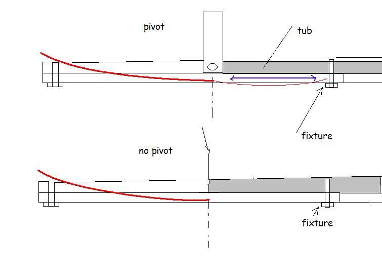
Image
Above we have a pivoted floor and a non pivoted floor being deflected.
Note that both have fixtures, the rear most fixture being behind the wear marks where it is claimed the floor is bending about.
Logic dictates that the floor will not pivot because of the rear fixture to the CFRP floor and tub. The plank is not free to move as it is fixed.
All will happen is the floor will cantilever about the pivot and a little sagging will take place behind the pivot. The sagging and deflection is shown with the red line. The sagging is probably on a minuscule order.
Compared to the non pivoted, the isn't any difference. The floor simply cantilevers where it meets the tub.

Now for the see saw to work, this needs to happen:
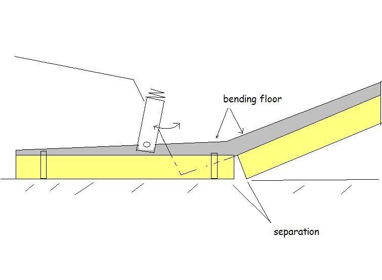
Image
the fasteners need to be on the part of the floor that is deflecting. Also the pivot has to be able to rotate to avoid the system being a simple cantilever as explained above. The pivot must also be sprung.
Also the separtion has to take place between the first and second piece of plank and the CFRP has to be considerably weak to bend in this joint.
Finaly the tub itselft needs a hollowed out section in the plank to shift into, keeping in mind the tub is flat on the bottom and it is still following the line of the the rest of the non pivoted floor. You can see this hollowed out part where the tub must go.
All of the above is illegal anyway.

Another method is this:
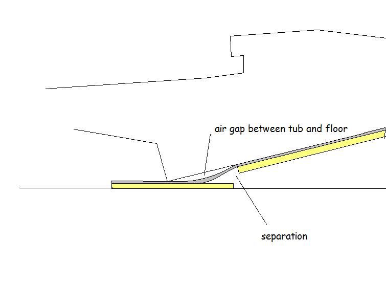
Image
This is self explanatory, and completely illegal and almost not plausible with a solid 1 piece CFRP floor. Note that the plank and floor has to be pulled away from the tub to move into place on the ground.

So in summary, simply cantelvering the floor is the logical means to this, which all teams are doing.

Using shape memory alloy, heat warp mechanics for composites, or whatever other technology is also a possibility.
For Sure!!

hardingfv32
hardingfv32
35
Joined: 03 Apr 2011, 19:42

Re: Scarbs T-Tray proposal

Post

Ringo wrote:

1) "Your experiment is not very accurate. It's demonstrative but not accurate.
The plank is attached to a carbon fiber floor remember."

Can you present better data?

This experiment demonstrates that the plank can bend when securely attached to the floor on it's ends to the floor. I used a test span similar to what we believe is require for the "see saw" system. The wood is multi layer birch laminate and of greater thickness than the actual plank. Birch is also stronger than beech wood used in Jabroc. I am using Jabroc as a reference, as we know this could or has been used in the past.

I clearly state that there is a large hole in the RB7 floor. This could be cover with a section of floor with almost no strength to comply with the rules. So, plank attachment to the floor does not restrict the use of the "see saw" system.

2) "You forget to mention that the plank has to move with the floor as it is fixed to it; we've seen the fasteners.
So the limiting factor is the strain in the carbon floor. CFRP has small strains and the plank's stretch will be limited to that of the CFRP floor."

The point of the experiment is to show that the wood fibers of a Jabroc plank have very good elongation properties.

Why can't the floor in the area critical to the "see saw" be fabricated with a material other than CF that has good elongation properties. The design of the lay orientation could also help the elongation goal.

3) "This is self explanatory, and completely illegal and almost not plausible with a solid 1 piece CFRP floor. Note that the plank and floor has to be pulled away from the tub to move into place on the ground."

A) Your last illustration is exactly what is required for the "see saw" system to function. Yes, it might not be possible with a solid 1 piece CFRP floor, BUT, we KNOW that the RB& has a hole in the floor and we DON'T KNOW that the floor is all CFRP.

B) To the legality issue:

"3.12.5 All parts lying on the reference and step planes, in addition to the transition between the two planes, must produce uniform, solid, hard, continuous, rigid (no degree of freedom in relation to the body/chassis unit),impervious surfaces under all circumstances."

As clear as this rule is, it is just as clear how it is being applied by the officials (up till this time). The FIA has a splitter (part of the floor) test where they clearly expect movement and provide a limit. So CLEARLY their definition of "no degree of freedom" allows for some movement. So regardless of how you read the rules, the "see saw" system could be considered legal by any reasonable designer under the circumstances that have applied to this rule in the past.

4) "Using shape memory alloy, heat warp mechanics for composites, or whatever other technology is also a possibility."

You still need to provide some track temp data before this thought can be evaluated. Mid day in the summer with a ambient of 38C, say clean new asphalt.

Brian

Richard
Richard
Moderator
Joined: 15 Apr 2009, 14:41
Location: UK

Re: Scarbs T-Tray proposal

Post

Or the simple option is that it is pre-cambered to the desired shape and squashed flat on the test rig.

Lift the car off the test rig and it springs back to a banana.

ps Ringo - I said in one of the first posts that I doubt a literal simple see-saw set up with a pure pivot. There has to be some continuity in order give the tray enough stiffness to stay in the team's desired position.

User avatar
ringo
230
Joined: 29 Mar 2009, 10:57

Re: Scarbs T-Tray proposal

Post

I agree. Pre cambered is possible, but it may be suspicious if the flatness of the reference plane is checked.

A) Your last illustration is exactly what is required for the "see saw" system to function. Yes, it might not be possible with a solid 1 piece CFRP floor, BUT, we KNOW that the RB& has a hole in the floor and we DON'T KNOW that the floor is all CFRP.
Which hole are you reffering to?
I think the floor is all CFRP. We have many images of the floor being lifted over walls. It looks like 1 solid strong piece. Torro Rosso's floor is also an example.

Answer this though.
Do you have evidence, out side of the scrape marks, that the car indeed sits on the plank on track?

Also answer this:

What is the logic in cutting flow under the floor to get the front wing closer to the ground.
Which one makes more downforce, the floor or the front wing?

The floor doesn't work if it come in contact with the ground, in fact it is best staying outside of the boundary layer.
The boundary layers thickness increases the furhther downstream the air flows.
So intermitent contact with the tip alone ins't detrimental, but placing 650mm of plank flat on the floor is in no way beneficial.
This adversely affects the ability of the floor to accelerate air flow.

Sacrificing floor down force just the get the wing down doesn't make sense.

There is a limit to getting the floor close. You only use as much rake that permits quality flow to travel under the car.

This is another reason why i don't buy into the the scrapes being an indication of the car riding on the splitter purposely.

I chalk it up to curb riding, debris, or topography in turns.
It's only in slightly cambered mid speed turns where i've heard the redbull of 2010 and 2009 scraping the ground momentarily.

Saying that, what is the aero benfit of placing 650mm of plank on the ground?
For Sure!!

hardingfv32
hardingfv32
35
Joined: 03 Apr 2011, 19:42

Re: Scarbs T-Tray proposal

Post

1) Pre camber beyond the tolerance of 10.98 mm would not satisfy the rules concerning the floors flatness.

2) The hole I am referring to is about 300 mm wide and maybe 400 mm long as seen in the RB7 pit crew lifting the floor in the pits at Monza this year.

Image

3) You have NO idea what the floor inner layer are, how thick, or the configurations of the laminates in the areas that would be important to this discussion.

4) No part of the plank sits on the track with the "see saw" system. The purpose is to run closer to the track surface WITHOUT incurring unacceptable wear. This allows the front wing to ride lower, the main goal. Most wear should be from track surface irregularities, curbs, etc.

5) I am not sure where the compromise is between the negatives (if they do exist) of the floor being to low at the entrance and the positives of the front wing being lower. I think it is logical to assume it is a net benefit if the RB7 is using this low floor setup.

6) You have been too casual about reading/following this thread. It was made clear very early in this discussion the goal of the "see saw" system is not to constantly ride on the track surface. The majority of your last post is therefore not relevant.

Have any NEW in the ways to challenges to the "see saw" theory?

Brian

User avatar
ringo
230
Joined: 29 Mar 2009, 10:57

Re: Scarbs T-Tray proposal

Post

I am retiring now, but there are many "holes" in your statement. :lol:
That hole is for the tub. Nothing else goes there. It doesn't qualify as a hole in the plank. So you are shifting your statement; grasping. :mrgreen:

Secondly it doesn't change a thing. It makes matters even worse for your case.
As the fixing bolts now go directly to the tub correct?

The driver's ass goes in that space there.

Notice how the hole is wider than the plank? This hole is merely for the tub.
The floor doesn't lose much strenght by the hole either as you can see the "T" shape is where most of the bending strength is.

What makes it even worse for you is that you are suggesting that the reference plane is in fact more than one plane As one will be angled to the other when the floor bends.
All of the plank must be on the reference plane at all times. If one pies is angled to the other by means of a mechanism, it is no longer in one plane.

If it is redbull are doing this:
Image
which is very unlikely due to the nature of the materials.

then it is illegal.

I don't think they though, becuase i've never seen the car on track doing what the see saw idea is suggesting. And the hole in the floor doesn't really support the idea. We still haven't seen the "seesaw" itself.
For Sure!!

User avatar
ringo
230
Joined: 29 Mar 2009, 10:57

Re: Scarbs T-Tray proposal

Post

hardingfv32 wrote:1) Pre camber beyond the tolerance of 10.98 mm would not satisfy the rules concerning the floors flatness.
Ask richard to explain that one.
3) You have NO idea what the floor inner layer are, how thick, or the configurations of the laminates in the areas that would be important to this discussion.
There barely 3mm of carbon there, what kind of sorcery do you think you can get in 3mm?
I don't think you should mention configurations if you aren't giving any examples.
I don't scare easy. Only facts can phase me. I see 3mm or less of material, not much room for sorcery in that.
4) No part of the plank sits on the track with the "see saw" system.

Really now, so how will it deflect? Didn't scarbs say the ground will push it up?
The purpose is to run closer to the track surface WITHOUT incurring unacceptable wear. This allows the front wing to ride lower, the main goal. Most wear should be from track surface irregularities, curbs, etc.
You are contradicting yourself. What's going to wear the plank, the air?
5) I am not sure where the compromise is between the negatives (if they do exist) of the floor being to low at the entrance and the positives of the front wing being lower. I think it is logical to assume it is a net benefit if the RB7 is using this low floor setup.
Again i don't see the conection if the seesaw works if the floor doesn't touch the ground. When you say low floor, you mean touching the ground do you?
6) You have been too casual about reading/following this thread. It was made clear very early in this discussion the goal of the "see saw" system is not to constantly ride on the track surface. The majority of your last post is therefore not relevant.
:lol: :lol: =D> I guess it's a real seesaw, it goes up and down.

You deeming my post irrelevant doesn't make it so. Most of your posts are just supercilious.
Have any NEW in the ways to challenges to the "see saw" theory?
You mean the conspiracy? I'm not challenging it. It's having a hard time holding up itself. It needs more see in it's saw.
For Sure!!

hardingfv32
hardingfv32
35
Joined: 03 Apr 2011, 19:42

Re: Scarbs T-Tray proposal

Post

Ringo wrote:

1) "There barely 3mm of carbon there, what kind of sorcery do you think you can get in 3mm?
I don't think you should mention configurations if you aren't giving any examples.
I don't scare easy. Only facts can phase me. I see 3mm or less of material, not much room for sorcery in that."

You have made it obvious on many occasions that the only facts you accept with are ones that agree with your position.

As for the 3 mm of material with elongation or flex as the goal, how about a rubberized interlay or low strength glass coated/tinted to look like carbon fiber. This is only a response to your sorcery question and does NOT imply any relevance to the subject of this thread.

2) "Really now, so how will it deflect? Didn't scarbs say the ground will push it up?"
"You are contradicting yourself. What's going to wear the plank, the air?"

Are these petty responses the sign of someone who is unable to defend his position? My statements are clear, the circumstances that cause wear for a standard plank will be the same for the plank of the "see saw" system.

3) "When you say low floor, you mean touching the ground do you?"

No, I mean a setup where the RB7's floor/plank is closer to the ground (on average/per lap) than all other competitors.

Brian

hardingfv32
hardingfv32
35
Joined: 03 Apr 2011, 19:42

Re: Scarbs T-Tray proposal

Post

Ringo wrote:

1) "That hole is for the tub. Nothing else goes there. It doesn't qualify as a hole in the plank. So you are shifting your statement"

Again, you either are not understanding this thread or you are grasping for any weak argument. My statement was clear that hole was if the floor and not in the plank.

2) "Secondly it doesn't change a thing. It makes matters even worse for your case."

The hole represents a flaw in your belief that the floor "looks like 1 solid strong piece" .

3) "As the fixing bolts now go directly to the tub correct?"

I say the fasteners go into an assembly that fills the hole in the floor.

4) "The floor doesn't lose much strength by the hole either as you can see the "T" shape is where most of the bending strength is."

I say the floor looses a lot of strength. While the "T" shape does add strength, we have no idea how much. The floors have had this basic shape for a long time, yet they now feel it is necessary to have a test to prevent excessive bending.

5) "What makes it even worse for you is that you are suggesting that the reference plane is in fact more than one plane As one will be angled to the other when the floor bends.
All of the plank must be on the reference plane at all times. If one pies is angled to the other by means of a mechanism, it is no longer in one plane."

If you are proposing that this would be illegal, that can be argued, BUT it will meet the dimensions set by the rules when the car in a static position for testing.

There is no rule that says the plank must be on the reference plane at all times.

6) "I don't think they though, because i've never seen the car on track doing what the see saw idea is suggesting."

Well, now this is true science.... I've have never seen it!

7) "We still haven't seen the "seesaw" itself"

I doubt your eyes would believe what they were seeing if you actually saw one.

Brian

Richard
Richard
Moderator
Joined: 15 Apr 2009, 14:41
Location: UK

Re: Scarbs T-Tray proposal

Post

ringo wrote:
hardingfv32 wrote:1) Pre camber beyond the tolerance of 10.98 mm would not satisfy the rules concerning the floors flatness.
Ask richard to explain that one.
If the stewerds measure tolerance with the plank sitting on the test rig as reported by Scarbs, the you'll have 650kg compressing it into alignment.

hardingfv32
hardingfv32
35
Joined: 03 Apr 2011, 19:42

Re: Scarbs T-Tray proposal

Post

1) There is no flatness specification for the plank, so the stewards do not make such measurements.

2) The floor has flatness requirements, but it is specified that the plank is removed when considering the dimensions of the floor. It is the very first sentence of the section pertaining to the floor.

You would measure the floor using a technique that allows access to all of the floor surface area. The floor sitting on a test surface or plane would not work.

Brian