- Login or Register
No account yet? Sign up
VIGVs are used to extend compressor range, as they allow to move surge line to the left.gruntguru wrote: ↑21 Sep 2022, 03:14You got it back to front. Non-rotating inlet flow will give best efficiency at only one point (or line of points) on the map. Movable vanes will give best efficiency at every point on the map and will NEVER be detrimental.saviour stivala wrote: ↑18 Sep 2022, 07:49‘’Swirl caused by angling the movable vanes will actually only improve efficiency at only one point on the map. Generally the effects are detrimental to the efficiency and linear flow is desirable.’’
https://www.airbestpractices.com/techno ... efficiency
Do you know for certain they’re using throttle bodies? Technically speaking it represents an efficiency loss in the system as it is a method of controlling engine rpm that works by increasing pumping losses on the intake.saviour stivala wrote: ↑21 Sep 2022, 07:43I got nothing back-to-front as I was as I stated ‘quoting trendy trend – fithecnical net forum 2006’. Read 3rd from top post (17 sept) on this page. According to trendy trend he was talking from actual personal dyno testing experience on the effects throttle bodies in front of turbo compressors on road going ICE.
Further= on road going turbocharged ICE compressor throttle bodies in front of compressor are used in conjunction with normal throttle bodies on ICE. They were added to reduce turbo-lag by inducing partial vacuum. This did two things:- firstly it allows the turbo to spin longer at higher rpm because of the reduced pumping losses. Secondly :- the partial vacuum helped accelerate the air through the impeller, rather then just relying on the impeller to pull-it through. The main throttle bodies (ICE) were retained because the response time to driver input is faster.
When you quote another source you should:saviour stivala wrote: ↑21 Sep 2022, 07:43I got nothing back-to-front as I was as I stated ‘quoting trendy trend – fithecnical net forum 2006’. Read 3rd from top post (17 sept) on this page. According to trendy trend he was talking from actual personal dyno testing experience on the effects throttle bodies in front of turbo compressors on road going ICE.
Further= on road going turbocharged ICE compressor throttle bodies in front of compressor are used in conjunction with normal throttle bodies on ICE. They were added to reduce turbo-lag by inducing partial vacuum. This did two things:- firstly it allows the turbo to spin longer at higher rpm because of the reduced pumping losses. Secondly :- the partial vacuum helped accelerate the air through the impeller, rather then just relying on the impeller to pull-it through. The main throttle bodies (ICE) were retained because the response time to driver input is faster.


Not really..saviour stivala wrote: ↑17 Sep 2022, 14:31Closing the movable vanes when driver lifts throttle will increase turbo rpm for a given turbine exhaust flow because with no airflow the compressor have less work to do, when driver returns on throttle the turbo higher rpm will eliminate turbo lag.

You would be surprised!!johnny comelately wrote: ↑22 Sep 2022, 02:52My whisper says: after much calculation and heavy discussion which took 8 seconds, this was arrived at. Admittedly for a non-offthrottle situation
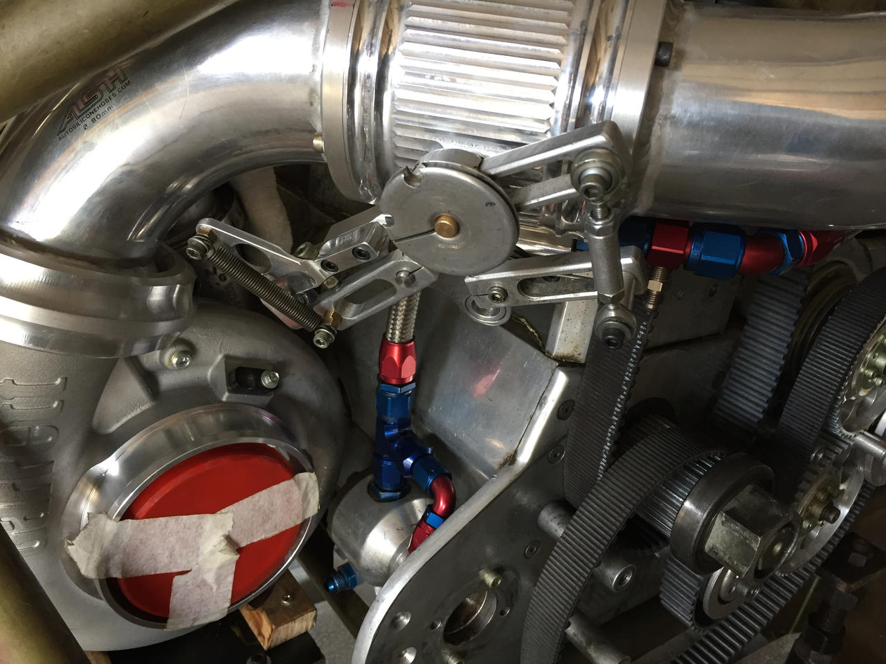
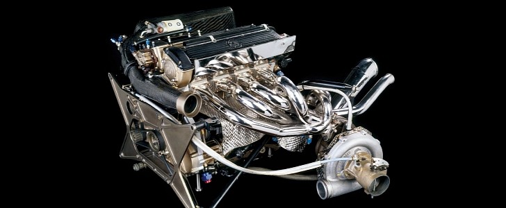
My archaic brain cannot think of any throttles on F1 engines before the turbo, if anyone has a picture of such I would be interested
https://images-wixmp-ed30a86b8c4ca88777 ... E7RI1fAWcU

The M12's major shortcoming as a Formula One engine was its lack of throttle response due to turbo lagPlatinumZealot wrote: ↑22 Sep 2022, 04:50You would be surprised!!johnny comelately wrote: ↑22 Sep 2022, 02:52My whisper says: after much calculation and heavy discussion which took 8 seconds, this was arrived at. Admittedly for a non-offthrottle situation
My archaic brain cannot think of any throttles on F1 engines before the turbo, if anyone has a picture of such I would be interested
https://images-wixmp-ed30a86b8c4ca88777 ... E7RI1fAWcU
https://s1.cdn.autoevolution.com/images ... 7344-7.jpg
why ?saviour stivala wrote: ↑22 Sep 2022, 04:22... putting a carburetor in front of a turbo is a sizable restriction.....
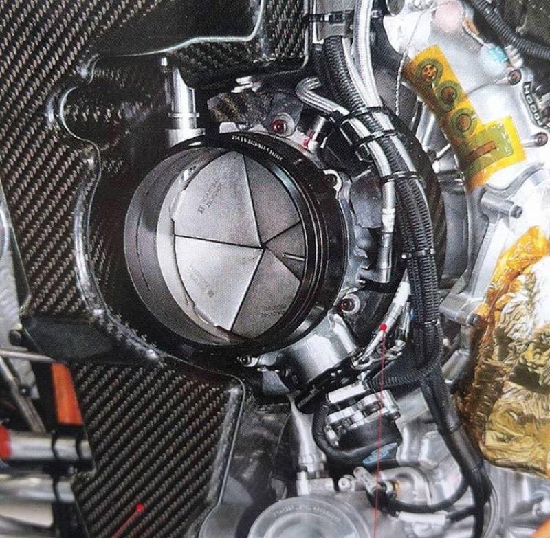
The thing is, looking at the actuation mechanism, the colar, it isn't possible for them to be closed, the maximum movement they seem to present is around 45 degrees.saviour stivala wrote: ↑21 Sep 2022, 21:42Out of the four different power unites used the only one I actually seen was the Mercedes. I do not remember the time but it was recently and on this forum, there was a Mercedes power unit photo showing the turbo compressor intake throttling system with all five vanes closed and marked one to five.
The photo I referred too which shows the vanes numbered one to five shows the vanes totally closed, of course the engine in that photo is not running, but that shows that in fact that they can close as in the photo. Now let us calmly dialogue this interesting subject, while keeping to the subject at hand. mine and my opinion only, first of all I believe that placing anything in front of the compressor air intake is in itself a restriction to that intake area. So the fact that they did not chose the camera iris system to throttle the intake which totally eliminates any intake restriction when fully open, means that they where willing to except the restriction of the five vane edges when fully open in front the turbo intake, for in turn getting some swirl. Although for the compressor to get some vacuum for the purpose of partially unloading the compressor and so maintain higher rpm, the vanes does not need to fully close, they only need start restricting the intake. Which leaves only the fully closed position question. Why fully close?. When driver goes off throttle (lifts) momentarily as it my be, the ICE throttles are fully closed. So no air is entering the cylinders, in this off throttle situation if the compressor intake throttle is not closed, a pop-up valve will have to be used. Further back in the thread, putting one’s hand on the intake of a vacuum cleaner nozzle example was given to unload the vacuum cleaner motor to spin faster.Clubman1d wrote: ↑22 Sep 2022, 19:46The thing is, looking at the actuation mechanism, the colar, it isn't possible for them to be closed, the maximum movement they seem to present is around 45 degrees.saviour stivala wrote: ↑21 Sep 2022, 21:42Out of the four different power unites used the only one I actually seen was the Mercedes. I do not remember the time but it was recently and on this forum, there was a Mercedes power unit photo showing the turbo compressor intake throttling system with all five vanes closed and marked one to five.
Even if they do manage to close, it doesn't seem the vane design covers all the frontal area.
After reading about it, Garret doesn't make a secret out of it, you're absolutely right.saviour stivala wrote: ↑22 Sep 2022, 20:51The photo I referred too which shows the vanes numbered one to five shows the vanes totally closed, of course the engine in that photo is not running, but that shows that in fact that they can close as in the photo. Now let us calmly dialogue this interesting subject, while keeping to the subject at hand. mine and my opinion only, first of all I believe that placing anything in front of the compressor air intake is in itself a restriction to that intake area. So the fact that they did not chose the camera iris system to throttle the intake which totally eliminates any intake restriction when fully open, means that they where willing to except the restriction of the five vane edges when fully open in front the turbo intake, for in turn getting some swirl. Although for the compressor to get some vacuum for the purpose of partially unloading the compressor and so maintain higher rpm, the vanes does not need to fully close, they only need start restricting the intake. Which leaves only the fully closed position question. Why fully close?. When driver goes off throttle (lifts) momentarily as it my be, the ICE throttles are fully closed. So no air is entering the cylinders, in this off throttle situation if the compressor intake throttle is not closed, a pop-up valve will have to be used. Further back in the thread, putting one’s hand on the intake of a vacuum cleaner nozzle example was given to unload the vacuum cleaner motor to spin faster.Clubman1d wrote: ↑22 Sep 2022, 19:46The thing is, looking at the actuation mechanism, the colar, it isn't possible for them to be closed, the maximum movement they seem to present is around 45 degrees.saviour stivala wrote: ↑21 Sep 2022, 21:42Out of the four different power unites used the only one I actually seen was the Mercedes. I do not remember the time but it was recently and on this forum, there was a Mercedes power unit photo showing the turbo compressor intake throttling system with all five vanes closed and marked one to five.
Even if they do manage to close, it doesn't seem the vane design covers all the frontal area.
