Andres125sx wrote:A windshield is a simply supported beam
Ehem, sorry, Andrés, with all due respect, nope.
A simply supported beam is not affixed to anything, in the sense that is free to rotate at both ends. It is supported by its own weight and it's restricted in the vertical plane at both ends and in the horizontal plane at only one support (it's free to expand horizontally at the other support).
You're probably wanting to say
a windshield is a cantilevered beam in a convertible and a fixed beam in a regular car.
Simply supported and cantilevered beams. A beam that can resist moments at both ends is called a fixed beam (not in the image)

[quote=""Andres125sx"]

That´s not a true cantilever, the suspended span makes cantilever arms work different way, they start working as compressed structures while a true cantilever works as a flexed one (compression at the lower side and traction at the upper one) with much higher moments at the support. [/quote]
I'm not sure where to start... [-o<
I'm the last person in this forum to invoke ipse dixit arguments (I hate when someone says "I know more than you, so you have to listen to me"), but, Andrés,
con todo respeto y mucho cariño, I've been designing bridges (and beams) for over 30 years (yes, I was born "before dogs were invented", more or less), so you have to listen to me...

So, I'm pretty, pretty,
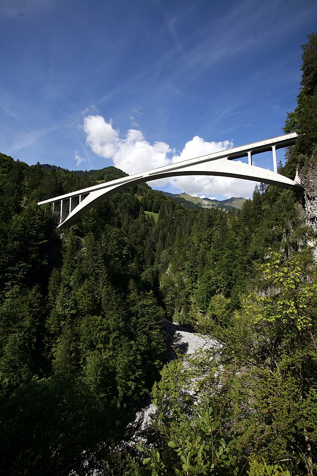
pretty sure that this bridge has a reduced moment compared with a simply supported one. I'm also pretty sure that's the critical design consideration.
However, I am a teacher, so let me add, emphatically, that it's perfectly understandable (what appears to be, at least for me) your confusion.
Actually, when the first bridge was designed like that, in the world famous Firth of Forth, there was so much misunderstanding (not to mention that the previous bridge has collapsed) that
the designer had to imagine a way to explain it in the simplest way possible.
If you're so kind, stay with me for a minute (yes, I know, my posts are loong and boring) and you will learn a couple of things, in case you have not learned them already.
If you have, then you perhaps will be enlightened about your knowledge.
There are no compressed structures on the beams of this bridge.
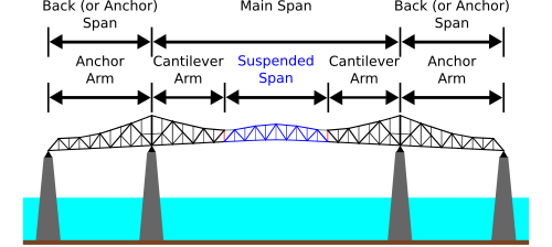
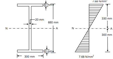
Both cantilevers have moment (what you call "compression at the lower side and traction (tension) at the upper one") , it's maximum at the ends of the beams closer to the center of the span and they are less than the moment you have in a simple beam.
At the intermediate supports you have shear, not compression.
The beams are cantilevered or affixed at the ends of the bridge, not at the columns.
Thus, at those pillars or columns, they need shear stirrups (vertical reinforcement: that is, the vertical squares at the right of the next image)...
Stirrups (estribos)

... instead of compression ties or hoops (horizontal reinforcement in the second following image).
Ties (aros en América Latina o presillas en España)

Now, the enlightenment:
Super-hyper-extra-majuscule-extraordinarily famous picture of the Firth of Forth bridge principle:
Ta daaaaaa!

Notice both guys at the extremes of the picture are working as true cantilevers: their arms are in tension in the upper part of the "beam" and the sticks that go from their hands to their hips are in compression in the lower part of the "beam". Quod erat demostratum...
 The end result: it's well done, I say, even for Scottish engineers...

I also want to remark that I put forward this bridge as an
example of a cantilevered design that is more efficient than a simply supported beam, not as an example of how you should analyze a windshield beam.
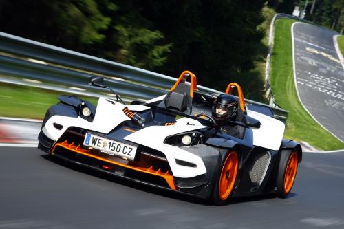
However, I insist, the critical factor in convertibles is the lack of rigidity of chassis, not windshield design.
Anyway, thanks for the opportunity to explain a couple of things about beams. I really love structural analysis, so, I think this thread is, as we say in Cali, "full HD".


