vorticism wrote: ↑13 May 2025, 14:26
There must be internal linkages added inboard which translate the transverse east-west linear motion of the steering rack...
There are not. The 2025 regs essentially state: "the inboard attachment points of the steering arms must maintain a fixed distance from each other, and only move in the y-axis (lateral direction)." So no linkages, it's just a plain rack and pinion mounted ~20 cm further back than normal, with arms swept by about 30 degrees. Q: are the effects of this beneficial to kinematics, or is it more about aero? Or by chance, beneficial to both.
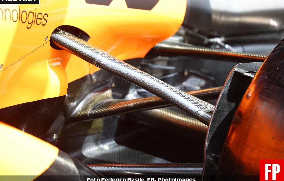
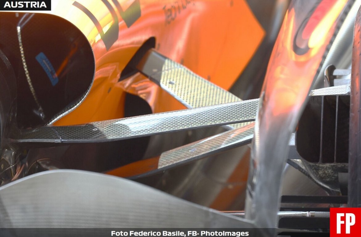
There was something interesting in the photos posted earlier. There's an unusual gold colored part on the upright near the ball joint of the steering arm. Haven't seen anyone address it online yet. It appears to be a slot with a pin passing through it. My guess is that this is a steering bump stop limiter. The pin would be an extension of the steering arm. The slot defines the maximum travel of the pin/maximum rotation of the upright. The pin itself could bend upon contact with the limit, providing a soft stop. If so, all normal behavior for such a device. Sketch below.
The acronym DAS is being thrown around, and by that what's meant is variable toe angle. This can't be done via anything upstream from the inner attachment points of the steering rack, per the regs mentioned above, which outlawed Merc-type DAS. If variable toe is being achieved it would have to be done through the suspension kinematics alone, or by some unknown loophole. It's all speculation, no one online has analyzed the motion of the front wheels yet.
What does stand out to me is the virtual kingpin axis, which seems like it could be rather far outboard. If it is beyond the contact patch then the tyre is being rolled across the contact patch rather than turned atop it i.e. reduced scrub when the wheels are turned. Basic suspension stuff, I only bring it up in the context of managing tire life/temps.


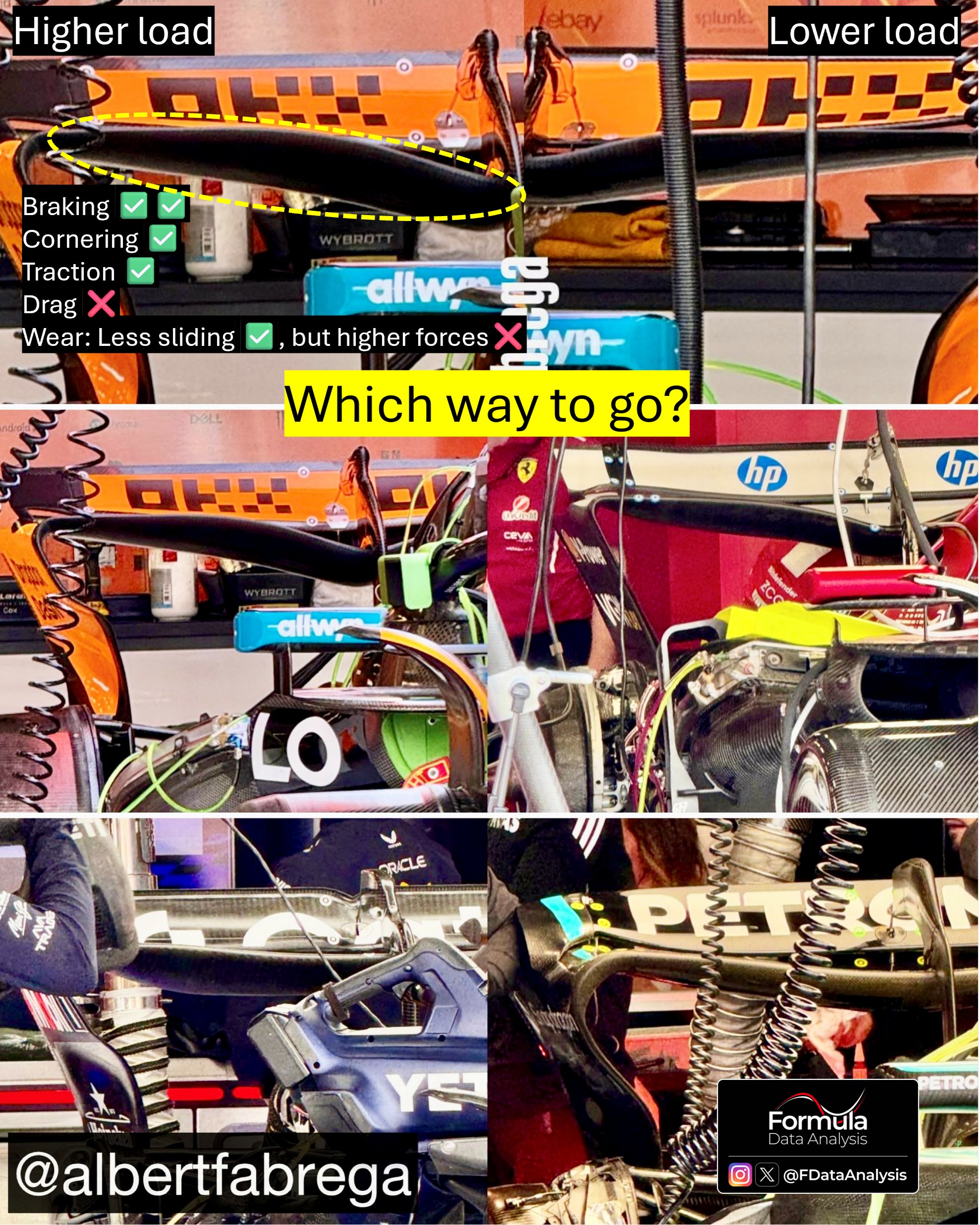


 Higher drag (main drawback)
 Smaller temperature spikes