CFD - 2022 Ferrari F1-75 (sidepod analysis)

Here are our CFD links and discussions about aerodynamics, suspension, driver safety and tyres. Please stick to F1 on this forum.
User avatar
Vanja #66
1562
Joined: 19 Mar 2012, 16:38

Re: Mercedes W13

Post

NoDivergence wrote:
23 Feb 2022, 21:38
I mean, your Merc W13 sidepod geometry is just wrong. Everything behind the inlet is different. The amount of downwash, the amount of outwash from the floor strakes, wavy floor exit, not having the right vortex flows from the front wing, etc etc. All of these have downstream effects that you're trying to make as simple as, oh the flow hits the tire and the rear wing has less downforce now.
How wrong? Quantify. Do you believe having an offset of 10mm on a sidepod of a 2000mm wide car can cause (or not cause) massive changes in overall major turublence structures? Let's see try something:

Image

Geometry just wrong? Hardly. Btw, do you have any idea how hard it is to achieve the corellation of that circled bottom separation?!? (I'd like to ask everyone to let NoDivergence answer this first, please. K thx)

NoDivergence wrote:
23 Feb 2022, 21:38
What angular velocity do you have the tires at in this model? And at what camber/castor/tire deformation geometry (which is a function of load)? Do you have the W13's reverse rake modeled?
Angular velocity is 138.9 rad/s. Does that mean anything to you without the free-stream velocity? That's kind of where things starts, isn't it?

What is the function of icluding tyre deformation? How can this be quantified? How can I guess this and is using my guess of any worth for this area? Or is it only worthy when using actual factual data which only teams and Pirelli have?

NoDivergence wrote:
23 Feb 2022, 21:38
All kinds of small details that can impact virtually everything of conclusion that you're trying to state
No, they can't. I'm not making any claims about floor performance for Heaven's sake...

NoDivergence wrote:
24 Feb 2022, 08:36
You may think that 10 times bigger may be sufficient to be statistically significant, but given that I'm 100% confident that your flow field is not accurate (front wing flow structure, bargeboard/vane/brake duct/floor geometry, sidepod geometry, etc, I wouldn't make any kind of claim if I were you. Vortex flow and wake management is the most complex part of these car's designs and have massive effects on the end results. I wouldn't be surprised if there was over 10% CDA difference between a completely unoptimized design like yours.(using standardized floor, wing, nose, etc letting the flo flow hit whatever it hits instead of being targeted and positioned) and something like what the W13 has, even in this testing state.
Bold part - Yes they are, they really are. When you are chasing a few more df points. I'm not chasing any df points really.

I wouldn't be surprised if there was even 15-20% CDA difference between this model and actual car. That doesn't mean that one model forming a structure the other isn't (and has no way of forming on the real car), causing a substantial difference in drag value, isn't a significant and telling sign.

NoDivergence wrote:
24 Feb 2022, 08:36
PS, one of the reasons for the amount of cranked front wing on the W13 is likely to maximize the amount of spanwise flow to power these vortices.

The concept of the sidepod cannot be separated from the optimizations intended to position these vortices and flow structures.

You mean to tell me that if I move the outwash an inch or several inches that the drag won't change significantly? How about if the car is at yaw? Or with the wheels turned and car is rolling?
Move the outwash a couple of inches within these regulations and teams will hire you instantly! :wink:

Expand your views my friend, CFD isn't the only tool an aerodynamicist should use. In fact, CFD is the slowest tool we use!
And they call it a stall. A STALL!

#DwarvesAreNaturalSprinters
#BlessYouLaddie

User avatar
dans79
267
Joined: 03 Mar 2013, 19:33
Location: USA

Re: Mercedes W13

Post

Vanja #66 wrote:
24 Feb 2022, 23:54
How wrong? Quantify. Do you believe having an offset of 10mm on a sidepod of a 2000mm wide car can cause (or not cause) massive changes in overall major turublence structures? Let's see try something:
Are you familiar with the concept of lyapunov exponent?

I've seen a dynamic system give completely different results when the initial conditions where changed by a miniscule amount (I'm talking in the 5 to 7 decimal place range type of change ), because the system was complex and very chaotic.
201 105 104 9 9 7

User avatar
AMG.Tzan
43
Joined: 24 Jan 2013, 01:35
Location: Greece

Re: Mercedes W13

Post

Vanja #66 wrote:
24 Feb 2022, 23:54
NoDivergence wrote:
23 Feb 2022, 21:38
I mean, your Merc W13 sidepod geometry is just wrong. Everything behind the inlet is different. The amount of downwash, the amount of outwash from the floor strakes, wavy floor exit, not having the right vortex flows from the front wing, etc etc. All of these have downstream effects that you're trying to make as simple as, oh the flow hits the tire and the rear wing has less downforce now.
How wrong? Quantify. Do you believe having an offset of 10mm on a sidepod of a 2000mm wide car can cause (or not cause) massive changes in overall major turublence structures? Let's see try something:

https://i.ibb.co/1RvSM1C/lewis-hamilton ... -w13-1.jpg

Geometry just wrong? Hardly. Btw, do you have any idea how hard it is to achieve the corellation of that circled bottom separation?!? (I'd like to ask everyone to let NoDivergence answer this first, please. K thx)

NoDivergence wrote:
23 Feb 2022, 21:38
What angular velocity do you have the tires at in this model? And at what camber/castor/tire deformation geometry (which is a function of load)? Do you have the W13's reverse rake modeled?
Angular velocity is 138.9 rad/s. Does that mean anything to you without the free-stream velocity? That's kind of where things starts, isn't it?

What is the function of icluding tyre deformation? How can this be quantified? How can I guess this and is using my guess of any worth for this area? Or is it only worthy when using actual factual data which only teams and Pirelli have?

NoDivergence wrote:
23 Feb 2022, 21:38
All kinds of small details that can impact virtually everything of conclusion that you're trying to state
No, they can't. I'm not making any claims about floor performance for Heaven's sake...

NoDivergence wrote:
24 Feb 2022, 08:36
You may think that 10 times bigger may be sufficient to be statistically significant, but given that I'm 100% confident that your flow field is not accurate (front wing flow structure, bargeboard/vane/brake duct/floor geometry, sidepod geometry, etc, I wouldn't make any kind of claim if I were you. Vortex flow and wake management is the most complex part of these car's designs and have massive effects on the end results. I wouldn't be surprised if there was over 10% CDA difference between a completely unoptimized design like yours.(using standardized floor, wing, nose, etc letting the flo flow hit whatever it hits instead of being targeted and positioned) and something like what the W13 has, even in this testing state.
Bold part - Yes they are, they really are. When you are chasing a few more df points. I'm not chasing any df points really.

I wouldn't be surprised if there was even 15-20% CDA difference between this model and actual car. That doesn't mean that one model forming a structure the other isn't (and has no way of forming on the real car), causing a substantial difference in drag value, isn't a significant and telling sign.

NoDivergence wrote:
24 Feb 2022, 08:36
PS, one of the reasons for the amount of cranked front wing on the W13 is likely to maximize the amount of spanwise flow to power these vortices.

The concept of the sidepod cannot be separated from the optimizations intended to position these vortices and flow structures.

You mean to tell me that if I move the outwash an inch or several inches that the drag won't change significantly? How about if the car is at yaw? Or with the wheels turned and car is rolling?
Move the outwash a couple of inches within these regulations and teams will hire you instantly! :wink:

Expand your views my friend, CFD isn't the only tool an aerodynamicist should use. In fact, CFD is the slowest tool we use!
No need to reply to anyone trying to lessen your work mate! People just cannot understand the energy it takes to create such a model let alone simulate the flows around it!!

Your work is outstanding and is just what this forum is all about! Simulation and Analysis!! :wink:

Btw, is there any way of simulating the underfloor's stalling that leads to porpoising?? It would give a nice picture of the vortices generated...
"The only rule is there are no rules" - Aristotle Onassis

cheeRS
cheeRS
10
Joined: 17 Jul 2018, 18:53

Re: Mercedes W13

Post

Vanja #66 wrote:
24 Feb 2022, 23:54
NoDivergence wrote:
23 Feb 2022, 21:38
I mean, your Merc W13 sidepod geometry is just wrong. Everything behind the inlet is different. The amount of downwash, the amount of outwash from the floor strakes, wavy floor exit, not having the right vortex flows from the front wing, etc etc. All of these have downstream effects that you're trying to make as simple as, oh the flow hits the tire and the rear wing has less downforce now.
How wrong? Quantify. Do you believe having an offset of 10mm on a sidepod of a 2000mm wide car can cause (or not cause) massive changes in overall major turublence structures? Let's see try something:

https://i.ibb.co/1RvSM1C/lewis-hamilton ... -w13-1.jpg

Geometry just wrong? Hardly. Btw, do you have any idea how hard it is to achieve the corellation of that circled bottom separation?!? (I'd like to ask everyone to let NoDivergence answer this first, please. K thx)

NoDivergence wrote:
23 Feb 2022, 21:38
What angular velocity do you have the tires at in this model? And at what camber/castor/tire deformation geometry (which is a function of load)? Do you have the W13's reverse rake modeled?
Angular velocity is 138.9 rad/s. Does that mean anything to you without the free-stream velocity? That's kind of where things starts, isn't it?

What is the function of icluding tyre deformation? How can this be quantified? How can I guess this and is using my guess of any worth for this area? Or is it only worthy when using actual factual data which only teams and Pirelli have?

NoDivergence wrote:
23 Feb 2022, 21:38
All kinds of small details that can impact virtually everything of conclusion that you're trying to state
No, they can't. I'm not making any claims about floor performance for Heaven's sake...

NoDivergence wrote:
24 Feb 2022, 08:36
You may think that 10 times bigger may be sufficient to be statistically significant, but given that I'm 100% confident that your flow field is not accurate (front wing flow structure, bargeboard/vane/brake duct/floor geometry, sidepod geometry, etc, I wouldn't make any kind of claim if I were you. Vortex flow and wake management is the most complex part of these car's designs and have massive effects on the end results. I wouldn't be surprised if there was over 10% CDA difference between a completely unoptimized design like yours.(using standardized floor, wing, nose, etc letting the flo flow hit whatever it hits instead of being targeted and positioned) and something like what the W13 has, even in this testing state.
Bold part - Yes they are, they really are. When you are chasing a few more df points. I'm not chasing any df points really.

I wouldn't be surprised if there was even 15-20% CDA difference between this model and actual car. That doesn't mean that one model forming a structure the other isn't (and has no way of forming on the real car), causing a substantial difference in drag value, isn't a significant and telling sign.

NoDivergence wrote:
24 Feb 2022, 08:36
PS, one of the reasons for the amount of cranked front wing on the W13 is likely to maximize the amount of spanwise flow to power these vortices.

The concept of the sidepod cannot be separated from the optimizations intended to position these vortices and flow structures.

You mean to tell me that if I move the outwash an inch or several inches that the drag won't change significantly? How about if the car is at yaw? Or with the wheels turned and car is rolling?
Move the outwash a couple of inches within these regulations and teams will hire you instantly! :wink:

Expand your views my friend, CFD isn't the only tool an aerodynamicist should use. In fact, CFD is the slowest tool we use!
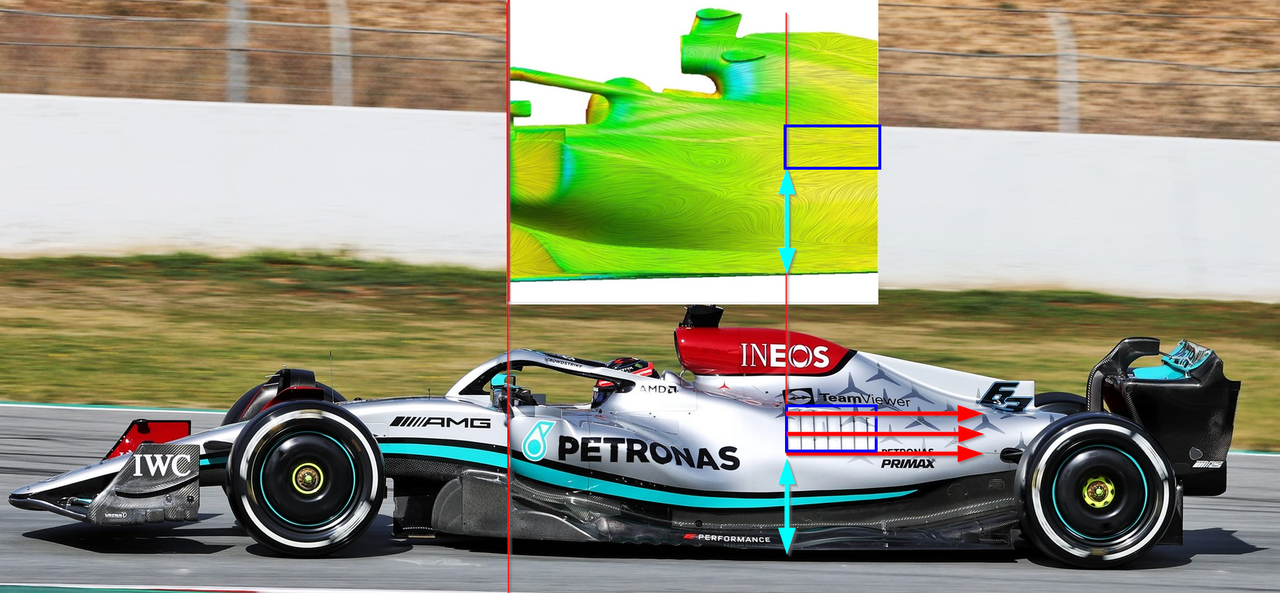
I won't pretend that I've read all the discussions regarding your models, but wow - seeing the similar... err... "aero lines" in your model and the real thing via flow viz is amazing. Nice work. THIS is why it's called F1technical here. =D>
Human history is the long terrible story of man trying to find something other than God which will make him happy.

User avatar
Vanja #66
1562
Joined: 19 Mar 2012, 16:38

Re: Mercedes W13

Post

dans79 wrote:
25 Feb 2022, 00:05
Are you familiar with the concept of lyapunov exponent?

I've seen a dynamic system give completely different results when the initial conditions where changed by a miniscule amount (I'm talking in the 5 to 7 decimal place range type of change ), because the system was complex and very chaotic.
Aerodynamics is a study of air movement. The air moves over the car (in a car reference system), generating changes in flow field, generating changes in static surface pressure. You generally don't want anything dynamic happening with this flow field or otherwise you have an unstable car or airplane or whatever, i.e. you want to have a static flow field as much as possible. Where not possible, you want to ensure the turbulence is predictable and controlled, nothing chaotic about it. Hence the tendency of teams to maneuver front tyre outwash away from the car etc.

AMG.Tzan wrote:
25 Feb 2022, 00:26
No need to reply to anyone trying to lessen your work mate! People just cannot understand the energy it takes to create such a model let alone simulate the flows around it!!

Your work is outstanding and is just what this forum is all about! Simulation and Analysis!! :wink:

Btw, is there any way of simulating the underfloor's stalling that leads to porpoising?? It would give a nice picture of the vortices generated...
Well, this is an online forum and we are here to exchange opinions and discuss. :) I learned a lot in the first few years I spent here and I feel I should give back to the best of my possibilities. This includes answering all kinds of questions and I'm not happy that I don't have the time to answer all of them to be honest, so I focus on the ones I see as a priority.

There is a difference between questioning anyone's work (including criticism, constructive or otherwise) and downright spitting on it. I question a lot of things myself and encourage questioning altogether. I don't allow anyone spitting on my or anyone else's work, be it good or not so good. :)

As for underfloor stall simulation, I can do the stall simulation if you want me to, but it's not of much use tbh. It might not look like anything that's actually going on on real cars and will look a lot like a generic diffuser stall, which you can see here

https://www.racetechmag.com/2017/08/wil ... diffusers/
And they call it a stall. A STALL!

#DwarvesAreNaturalSprinters
#BlessYouLaddie

User avatar
DAMNINice
37
Joined: 16 Feb 2012, 08:50

Re: Mercedes W13

Post

Vanja #66 wrote:
24 Feb 2022, 23:54

Expand your views my friend, CFD isn't the only tool an aerodynamicist should use. In fact, CFD is the slowest tool we use!
Hi Vanja,
really great Job!!

I was really confused by the layout of the gills of the Mercedes as they normally follow the path of the air to try and keep disruption of airflow to a minimum.
The way they are done on the Mercedes looked way too horizontal and idealised to me BUT... thanks to you, it is actually very obvious that their sidepod design is creating a very nice horizontal flow.
So not only are their gills positioned correctly (shame on me that I have questioned them :) ) But they have created a design which creates an absolute dream of an airflow to the rear wing!

Image
REal men play with twins!

ryaan2904
ryaan2904
36
Joined: 01 Oct 2020, 09:45

Re: Mercedes W13

Post

mantikos wrote:
24 Feb 2022, 19:23
kfrantzios wrote:
24 Feb 2022, 19:04
cplchanb wrote:
24 Feb 2022, 18:21


While we appreciate your efforts and zeal, as people have mentioned, the full car needs to be analyzed in order to have the complete picture, not just the side pods or part of the car. AFAIK, the only people other than the teams and those who have the Williams app that has the full car model is the fia technical dept. Not to mention the computational power required for these cfds, so unless you work in a lab with a super computer, it won't be completely accurate, at least not enough to make such a strong claim
Just a note regarding CFD…
CFD does not “teach” you aerodynamics. It is used to validate and optimise a concept. You need to get the concept right in the first place. Do you think that Adrian Newey or any other top designer need CFD simulations to understand flow?

In a scientific point of view, Vanja made a claim and run a simulation to prove it. While the argument that his simulation is not very accurate, as posted by others, is probably correct, it does not prove that the simulation and his claim is wrong.
And we aren't claiming his experiment to prove a hypothesis is wrong - that's the scientific method and we admire him for doing that.

What the rest of us are saying is that it doesn't represent the Mercedes car and therefore isn't directly applicable (and I believe you are saying that too but don't want to put those words in your mouth). So his claim about the W13 is off, however it is accurate about his model.

So basically the guy accepts that his earlier claim about Vanja's analysis being totally invalid was a personal opinion (no facts), and a wrong one at that. Took his statement back basically.

What a bs way to go about it tho. Called a bunch of his friends, threw about bs in other directions, but accepted in the end.
Could've just said you wanted to feel the w13 isnt draggy and you didn't really read Vanja's analysis before.
CFD Eyes of Sauron

User avatar
Vanja #66
1562
Joined: 19 Mar 2012, 16:38

Re: Mercedes W13

Post

DAMNINice wrote:
25 Feb 2022, 09:37
I was really confused by the layout of the gills of the Mercedes as they normally follow the path of the air to try and keep disruption of airflow to a minimum.
The way they are done on the Mercedes looked way too horizontal and idealised to me BUT... thanks to you, it is actually very obvious that their sidepod design is creating a very nice horizontal flow.
So not only are their gills positioned correctly (shame on me that I have questioned them :) ) But they have created a design which creates an absolute dream of an airflow to the rear wing!

https://i.postimg.cc/XqPX6P62/2022-02-2 ... 0-1280.png
Woah, nice catch! But seeing that much separation bellow this area that shouldn't be there on the actual car, I think this was a bit of a happy coincidence. :) In this case, it's the other ways around - the fact that those gills are aligned like that on the car gives some credibility to the CFD flow field. This is from David Penner's awesome LinkedIn post on 2021 Williams and shows how the streamlines should look on sidepods like this.

Image
And they call it a stall. A STALL!

#DwarvesAreNaturalSprinters
#BlessYouLaddie

NoDivergence
NoDivergence
50
Joined: 02 Feb 2011, 01:52

Re: Mercedes W13

Post

Vanja #66 wrote:
24 Feb 2022, 23:54
NoDivergence wrote:
23 Feb 2022, 21:38
I mean, your Merc W13 sidepod geometry is just wrong. Everything behind the inlet is different. The amount of downwash, the amount of outwash from the floor strakes, wavy floor exit, not having the right vortex flows from the front wing, etc etc. All of these have downstream effects that you're trying to make as simple as, oh the flow hits the tire and the rear wing has less downforce now.
How wrong? Quantify. Do you believe having an offset of 10mm on a sidepod of a 2000mm wide car can cause (or not cause) massive changes in overall major turublence structures? Let's see try something:

https://i.ibb.co/1RvSM1C/lewis-hamilton ... -w13-1.jpg

Geometry just wrong? Hardly. Btw, do you have any idea how hard it is to achieve the corellation of that circled bottom separation?!? (I'd like to ask everyone to let NoDivergence answer this first, please. K thx)

NoDivergence wrote:
23 Feb 2022, 21:38
What angular velocity do you have the tires at in this model? And at what camber/castor/tire deformation geometry (which is a function of load)? Do you have the W13's reverse rake modeled?
Angular velocity is 138.9 rad/s. Does that mean anything to you without the free-stream velocity? That's kind of where things starts, isn't it?

What is the function of icluding tyre deformation? How can this be quantified? How can I guess this and is using my guess of any worth for this area? Or is it only worthy when using actual factual data which only teams and Pirelli have?

NoDivergence wrote:
23 Feb 2022, 21:38
All kinds of small details that can impact virtually everything of conclusion that you're trying to state
No, they can't. I'm not making any claims about floor performance for Heaven's sake...

NoDivergence wrote:
24 Feb 2022, 08:36
You may think that 10 times bigger may be sufficient to be statistically significant, but given that I'm 100% confident that your flow field is not accurate (front wing flow structure, bargeboard/vane/brake duct/floor geometry, sidepod geometry, etc, I wouldn't make any kind of claim if I were you. Vortex flow and wake management is the most complex part of these car's designs and have massive effects on the end results. I wouldn't be surprised if there was over 10% CDA difference between a completely unoptimized design like yours.(using standardized floor, wing, nose, etc letting the flo flow hit whatever it hits instead of being targeted and positioned) and something like what the W13 has, even in this testing state.
Bold part - Yes they are, they really are. When you are chasing a few more df points. I'm not chasing any df points really.

I wouldn't be surprised if there was even 15-20% CDA difference between this model and actual car. That doesn't mean that one model forming a structure the other isn't (and has no way of forming on the real car), causing a substantial difference in drag value, isn't a significant and telling sign.

NoDivergence wrote:
24 Feb 2022, 08:36
PS, one of the reasons for the amount of cranked front wing on the W13 is likely to maximize the amount of spanwise flow to power these vortices.

The concept of the sidepod cannot be separated from the optimizations intended to position these vortices and flow structures.

You mean to tell me that if I move the outwash an inch or several inches that the drag won't change significantly? How about if the car is at yaw? Or with the wheels turned and car is rolling?
Move the outwash a couple of inches within these regulations and teams will hire you instantly! :wink:

Expand your views my friend, CFD isn't the only tool an aerodynamicist should use. In fact, CFD is the slowest tool we use!
So your model shows that the higher pressure flow goes to the low pressure in the cockpit? Congrats. Your model doesn't show nearly the amount of upwash though. And the circulation around the front of the sidepod is expected, you have a large stagnation at the underside of the inlet and a rectangular geometry interacting with a radiused floor leading edge.

PS, I'm not saying your axial positioning is wrong. The top down planform is, and so is the shape behind the inlet. Just look at it, way more downwash slope on the W13. And even if (it isn't) the flow stream on the body work was 100% correct, the outward free streams still aren't due to as I've said before, your vorticity. Body freestreams are easier to match as nobody is putting vortices there with body flow latching. And yes, tire deformation is very critical to flow field in tire squirt regions

PS, your sidepod "bargeboard" by the motor bargeboard is quite far off, and yes I'd state that due to the amount of curvature in that area, that can be a significant difference in outwash. Not to mention the floor and strake angles and front wing endplate. Wouldn't be surprised at all if the the outwash was an inch or more further outward than what your have

You cannot separate sidepod concept from the rest of the car. They are not independent variables and the system is way more complex than you are trying to make it out by stating one sidepod concept inherently is less draggy than the other. Admitting your error bar can be over 15% the total drag of the car right off the bat should tell you that those kinds of statements are meaningless.

And that admission by itself suggests you know your flow field is not accurate.

Just because one concept develops a means to reduce drag through a flow structure that can't be replicated on another doesn't mean the end result isn't the same. Mercedes has a solution through outwash that can reduce drag as well.

Those vortices don't just add df points. They can reduce drag too. It all depends on where they're pointed and how strong they are.

No Merc aero engineer is shaping bodywork and just letting vortices go wherever they want. But that's pretty much what you're doing in your model.

You mean to tell me if you changed component geometry by 0.5" that that wouldn't significantly affect your results? How about on a wing? Your wing geometry is off by at least that. And does not the wing affect every downstream flow structure?
Last edited by NoDivergence on 25 Feb 2022, 10:43, edited 2 times in total.

User avatar
DAMNINice
37
Joined: 16 Feb 2012, 08:50

Re: Mercedes W13

Post

Can we please either get closer to the W13 analysis when talking about the CFD as this whole thing starts to become a pissing contest which does not help anyone.

So let's close this by agreeing to:
1. Thanks to Vanja for taking the time to create the model and giving us some results.
2. It is obviously not 100% the W13 so results should be taken with a pinch of salt
3. Everyone knows that there is a differentiation of discussing generaly concepts (where this moderately accurate CFD analysis might help) while there is always the chance that 1mm wrong on the front wing can create a big knock on effect further downstream.

Now that we agreed to it we can stop arguing and start duscussing the stuff we see.

PS: I would say... if you are so certain, that the results are bollocks, either stop discussing them OR do your own homework and create your own 100% model of the W13 (good luck with that). We are looking forward to it!
REal men play with twins!

miguelalvesreis
miguelalvesreis
17
Joined: 12 May 2012, 13:38

Re: Mercedes W13

Post

DAMNINice wrote:
25 Feb 2022, 10:27
Can we please either get closer to the W13 analysis when talking about the CFD as this whole thing starts to become a pissing contest which does not help anyone.

So let's close this by agreeing to:
1. Thanks to Vanja for taking the time to create the model and giving us some results.
2. It is obviously not 100% the W13 so results should be taken with a pinch of salt
3. Everyone knows that there is a differentiation of discussing generaly concepts (where this moderately accurate CFD analysis might help) while there is always the chance that 1mm wrong on the front wing can create a big knock on effect further downstream.

Now that we agreed to it we can stop arguing and start duscussing the stuff we see.

PS: I would say... if you are so certain, that the results are bollocks, either stop discussing them OR do your own homework and create your own 100% model of the W13 (good luck with that). We are looking forward to it!

Right on!!! Absolutely agree!!!

NoDivergence
NoDivergence
50
Joined: 02 Feb 2011, 01:52

Re: Mercedes W13

Post

DAMNINice wrote:
25 Feb 2022, 10:27
Can we please either get closer to the W13 analysis when talking about the CFD as this whole thing starts to become a pissing contest which does not help anyone.

So let's close this by agreeing to:
1. Thanks to Vanja for taking the time to create the model and giving us some results.
2. It is obviously not 100% the W13 so results should be taken with a pinch of salt
3. Everyone knows that there is a differentiation of discussing generaly concepts (where this moderately accurate CFD analysis might help) while there is always the chance that 1mm wrong on the front wing can create a big knock on effect further downstream.

Now that we agreed to it we can stop arguing and start duscussing the stuff we see.

PS: I would say... if you are so certain, that the results are bollocks, either stop discussing them OR do your own homework and create your own 100% model of the W13 (good luck with that). We are looking forward to it!
1. Completely agreed
2. Yep
3. The second part of your statement should definitely be emphasized. Especially when talking about trying to state effects on the downstream structure (rear tire stagnation...)

To your PS, I don't have the resources to do a representative CFD of the W13, and frankly, nobody does outside of the F1 teams. Not even someone like Kyle who worked there before. I know just how much work went into Vanya's models, been there before. But to take conclusions on such a singular feature that's in the middle of the car with inaccurate pieces all around just isn't sensical. Mercedes isn't intending the sidepod by itself to have enough outwash to mitigate the drag on the rear tire. And yet that's essentially what this model conclusion is comparing

User avatar
DAMNINice
37
Joined: 16 Feb 2012, 08:50

Re: Mercedes W13

Post

NoDivergence wrote:
25 Feb 2022, 10:33
DAMNINice wrote:
25 Feb 2022, 10:27
Can we please either get closer to the W13 analysis when talking about the CFD as this whole thing starts to become a pissing contest which does not help anyone.

So let's close this by agreeing to:
1. Thanks to Vanja for taking the time to create the model and giving us some results.
2. It is obviously not 100% the W13 so results should be taken with a pinch of salt
3. Everyone knows that there is a differentiation of discussing generaly concepts (where this moderately accurate CFD analysis might help) while there is always the chance that 1mm wrong on the front wing can create a big knock on effect further downstream.

Now that we agreed to it we can stop arguing and start duscussing the stuff we see.

PS: I would say... if you are so certain, that the results are bollocks, either stop discussing them OR do your own homework and create your own 100% model of the W13 (good luck with that). We are looking forward to it!
1. Completely agreed
2. Yep
3. The second part of your statement should definitely be emphasized. Especially when talking about trying to state effects on the downstream structure (rear tire stagnation...)

To your PS, I don't have the resources to do a representative CFD of the W13, and frankly, nobody does outside of the F1 teams. Not even someone like Kyle who worked there before
I don't have the resources to do a representative CFD of the W13, and frankly, nobody does outside of the F1 teams.
--> Thats why I wrote it.

Which means the first part of my sentense occurs.
For this thread it means that you have the opinion that the effect on rear tire etc. is not representative on Vanjas CFD so it should not be discussed back and forth.

Back to W13: I'm a bit interested in another part of the floor the aero experts in here can share their thoughts on.

While to me, the outer lower throat + bargeboard + outwash of the sidepod + waveform on the floor edge is mostly there to create a vortex to seal the floor (If you have another idea of what the wavey edge is doing, please share your thoughts) I am missing a bit the possibility to refeed the floor with high energy air as all the other teams are doing.
Mercedes neither has a cutout at the middle part of the floor nor do they have the typical cutout just infront of the rear wheel.

What does that mean? I guess they need to feed the floor differently but I don't see how (other than the possibly high energy vortex by their stepped front wing which might lead into the floor entrance. But I am a bit puzzled.
REal men play with twins!

NoDivergence
NoDivergence
50
Joined: 02 Feb 2011, 01:52

Re: Mercedes W13

Post

NoDivergence wrote:
25 Feb 2022, 10:33
DAMNINice wrote:
25 Feb 2022, 10:27
Can we please either get closer to the W13 analysis when talking about the CFD as this whole thing starts to become a pissing contest which does not help anyone.

So let's close this by agreeing to:
1. Thanks to Vanja for taking the time to create the model and giving us some results.
2. It is obviously not 100% the W13 so results should be taken with a pinch of salt
3. Everyone knows that there is a differentiation of discussing generaly concepts (where this moderately accurate CFD analysis might help) while there is always the chance that 1mm wrong on the front wing can create a big knock on effect further downstream.

Now that we agreed to it we can stop arguing and start duscussing the stuff we see.

PS: I would say... if you are so certain, that the results are bollocks, either stop discussing them OR do your own homework and create your own 100% model of the W13 (good luck with that). We are looking forward to it!
1. Completely agreed
2. Yep
3. The second part of your statement should definitely be emphasized. Especially when talking about trying to state effects on the downstream structure (rear tire stagnation...)

To your PS, I don't have the resources to do a representative CFD of the W13, and frankly, nobody does outside of the F1 teams. Not even someone like Kyle who worked there before. I know just how much work went into Vanya's models, been there before. But to take conclusions on such a singular feature that's in the middle of the car with inaccurate pieces all around just isn't sensical. Mercedes isn't intending the sidepod by itself to have enough outwash to mitigate the drag on the rear tire. And yet that's essentially what this model conclusion is comparing
Is that what everyone else's floors are doing? I was under the impression that those cutouts/flaps/waves (forward/mid floor region) were all used to prevent flow from getting under the floor near the throat of the diffuser and the features/cutouts/etc in front of the rear tire are to control the tire squirt. From what I could see, the keyhole between the diffuser and tire of the Merc diffuser sidewall is bigger than most other teams. And they're trying to maximize the surface area of that side floor to have a mini diffuser and suck it closer to the ground

User avatar
Vanja #66
1562
Joined: 19 Mar 2012, 16:38

Re: Mercedes W13

Post

NoDivergence wrote:
25 Feb 2022, 09:54
Just because one concept develops a means to reduce drag through a flow structure that can't be replicated on another doesn't mean the end result isn't the same. Mercedes has a solution through outwash that can reduce drag as well.
I enjoyed replying to your previous comments, but right now I'm getting a feeling you are trying to run me in circles, throwing expressions and stuff out there without replying to my simple and direct questions or providing any other kind of quantification. So I will end this debate from my side with a reply to this section and won't return to this debate anymore. I will also ask the mods to move the bulk of this conversation to the topic dedicated to these CFD analyses.

In any case, I'll be short and use the best F1 CFD results we have available for direct comparison. Once again, these are from David Penner's amazing LinkedIn article. To compare the tyre drag in the best visual way possible I will post his bottom view results, my micro-pods results (related to W13) and tub-pods results (F1-75 related). I've set my results to Cp [-3, +1] distribution for absolute direct comparison, even if the bar colour-scheme is a bit different.

Image

Image

Image

There is a clear and almost full similarity between pressure distribution on his Williams rear tyre and my micro-pods rear tyre. This comes from very similar flow field ahead of both of these rear tyres - suggesting without any doubt that these launch spec W13 sidepods work very much like this concept did last year. I cannot make this any clearer if a person doesn't not want to accept obvious facts.

Compare this to tub-pods rear tyre pressure distribution and you will note a large difference in stagnation pressure, where the difference of 17% in rear tyre drag comes from. Heck, even take a look at front tyres! How different are those distributions? 100% or less than 1%? Even with very different front wings.

Opposite of what you are trying to state, I'm stating and have shown that W13 sidepods work a lot like W12 did regarding rear tyre conditioning. I'm also stating that F1-75 sidepods are doing something very different and I'm being very generous saying that W13 and F1-75 drag difference might be 5% since I believe this figure is closer to 10% when every other difference is taken into account.

In total, front and rear tyre drag with micro-pods model was 48% of overall drag. With tub-pods it was 45%, as the entire car drag was about 10% lower than micro-pods. Tyres excluded, both models generated almost the same amount of drag, less than 1% difference. F1-75 has a bigger front wing frontal projection, which is why I don't think the overall drag difference is more than 10% and since I can't be of right mind stating my tub-pods simulation is comparable enough to F1-75, I'm stating the difference in drag is only 5% or more.
And they call it a stall. A STALL!

#DwarvesAreNaturalSprinters
#BlessYouLaddie