Red Bull RB20

A place to discuss the characteristics of the cars in Formula One, both current as well as historical. Laptimes, driver worshipping and team chatter do not belong here.
User avatar
vorticism
323
Joined: 01 Mar 2022, 20:20

Re: Red Bull RB20

Post

djos wrote:
18 Feb 2024, 22:51
I agree that the ram effect is not useful for the turbo cars, what is useful is the cleaner, cooler air you get from that location. It’s my understanding that there is a fairly large temperature delta, especially when running behind other cars.
A reliable strata of cooler ~1 m elevation air will generally only be present in clean/still air (not following another car). When following another car the air will be churned (wake/dirty air) which contains a mix of radiator outflow, warmer track proximal air, and cooler higher elevation air; now determine if that mix is higher temp than clean/static 1m elevation air. As such, lowered engine air intakes would seemingly be mainly disadvantaged in clean air.
𓄀

User avatar
djos
113
Joined: 19 May 2006, 06:09
Location: Melbourne, Australia

Re: Red Bull RB20

Post

vorticism wrote:
19 Feb 2024, 01:27
djos wrote:
18 Feb 2024, 22:51
I agree that the ram effect is not useful for the turbo cars, what is useful is the cleaner, cooler air you get from that location. It’s my understanding that there is a fairly large temperature delta, especially when running behind other cars.
A reliable strata of cooler ~1 m elevation air will generally only be present in clean/still air (not following another car). When following another car the air will be churned (wake/dirty air) which contains a mix of radiator outflow, warmer track proximal air, and cooler higher elevation air; now determine if that mix is higher temp than clean/static 1m elevation air. As such, lowered engine air intakes would seemingly be mainly disadvantaged in clean air.
On the current cars, the dirty air effect doesn't seem to "hang in the air" as far back as it used too - I guess I'm basing my theory on vision like this (and I agree, it's hard to compare dampness levels, so I tried to pick photos showing a dry racing line):

Image

vs

Image
"In downforce we trust"

Mmgnt
Mmgnt
1
Joined: 19 Feb 2023, 06:57

Re: Red Bull RB20

Post

DRCorsa wrote:
18 Feb 2024, 17:27
Here's my opinion on the RB20.
The current sidepods are dummies.
The radiators are placed inside the cannons and the inlet air goes upward to the radiators. That's why their inlet is below and facing upwards.
Later they will just bring the smaller sidepods that will only be used just as airflow conditioning devices. They can do whatever they want with those "sidepods".

https://i.ibb.co/qxfV5mc/RB20.png
I've been wondering the same. Check out the bulge up front...

Image

AR3-GP
AR3-GP
365
Joined: 06 Jul 2021, 01:22

Re: Red Bull RB20

Post

Mmgnt wrote:
19 Feb 2024, 03:20
DRCorsa wrote:
18 Feb 2024, 17:27
Here's my opinion on the RB20.
The current sidepods are dummies.
The radiators are placed inside the cannons and the inlet air goes upward to the radiators. That's why their inlet is below and facing upwards.
Later they will just bring the smaller sidepods that will only be used just as airflow conditioning devices. They can do whatever they want with those "sidepods".

https://i.ibb.co/qxfV5mc/RB20.png
I've been wondering the same. Check out the bulge up front...

https://i.imgur.com/3VB1Avg.jpeg
I'm throwing this out there with zero intuition, but could the s-duct exit above? Is there any reason to do that? Maybe that is why there are bulges inside the cockpit tunnel? If the purpose of the gulley is to contain the cockpit losses, then perhaps dumping the chassis losses in this area makes sense as well?
Image
A lion must kill its prey.

User avatar
organic
1055
Joined: 08 Jan 2022, 02:24
Location: Cambridge, UK

Re: Red Bull RB20

Post

AR3-GP wrote:
19 Feb 2024, 03:27
Mmgnt wrote:
19 Feb 2024, 03:20
DRCorsa wrote:
18 Feb 2024, 17:27
Here's my opinion on the RB20.
The current sidepods are dummies.
The radiators are placed inside the cannons and the inlet air goes upward to the radiators. That's why their inlet is below and facing upwards.
Later they will just bring the smaller sidepods that will only be used just as airflow conditioning devices. They can do whatever they want with those "sidepods".

https://i.ibb.co/qxfV5mc/RB20.png
I've been wondering the same. Check out the bulge up front...

https://i.imgur.com/3VB1Avg.jpeg
I'm throwing this out there with zero intuition, but could the s-duct exit above? Is there any reason to do that? Maybe that is why there are bulges inside the cockpit tunnel?
There's not a huge amount of freedom in terms of outlet location. It needs to be within the intersection of the louvre aperture volume with the mid-chassis volume. Looking at this, I don't think it would allow you to have it in the bulging regions next to the roll hoop - the max height of that intersection is not going to let you have the outlet up there. Then again RB might be able to make it work through different rules but if you go by how ferrari did it i dont think its going to work
Last edited by organic on 19 Feb 2024, 03:35, edited 1 time in total.

Mmgnt
Mmgnt
1
Joined: 19 Feb 2023, 06:57

Re: Red Bull RB20

Post

Here's my guess: there are small rads in the sidepods, as well as somewhere in the cannon area. The S-ducts flow into the cannons, coming up at the bulge.

The seating location appears to permit it as it'd be behind the driver seat/shoulders

Looking at the comparison pic again, those cannons are just way too huge to not have something significant underneath IMO. They even bulge out immediately after the halo mount, as soon as possible (I assume, given Halo mounting restrictions). From an aero perspective I assume this would introduce unnecessary drag, meaning they must have a reason?

It also looks like it might fit between seat & fuel cell? Not sure what's there (carbon area in front of the light brown cell)

Image
Image
Image
Image

venkyhere
venkyhere
14
Joined: 10 Feb 2024, 06:17

Re: Red Bull RB20

Post

Vanja #66 wrote:
18 Feb 2024, 12:03
LM10 wrote:
18 Feb 2024, 09:58
Wouldn’t this shift the balance of the car and require changes to other areas (especially in the front) of the car as well?
Both wings are about 4-5 times further away longitudinally from CoG than any surface on the sides. Basically 2-3 clicks on the front wing and all good to go, these changes would bring more on drag reduction than downforce increase.
=D> to Vanja's illustration, makes a lot of sense, slight coanda above the newly added 'eagle-beak' of the overbite shoudn't really 'affect' the overall attached flow above the upper downramp of the sidepod, just that it will be a bit slower. Which brings LM10's point about the overall center of pressure shifting rearwards slightly, demanding more 'clicks' from the front wing, as per Vanja's answer.

But then, wont this create a recursive loop ? More clicks in front wing => more upwash => the eagle-beak starts to be less effective => dial the curvature of eagle-beak back at bit => center of pressure now shifts forwards a bit => now dial back the front wing clicks => eagle-beak is now more effective... back to square 1.

PhF1x
PhF1x
1
Joined: 09 Dec 2023, 15:31

Re: Red Bull RB20

Post

Mmgnt wrote:
19 Feb 2024, 04:14
Here's my guess: there are small rads in the sidepods, as well as somewhere in the cannon area. The S-ducts flow into the cannons, coming up at the bulge.

The seating location appears to permit it as it'd be behind the driver seat/shoulders

Looking at the comparison pic again, those cannons are just way too huge to not have something significant underneath IMO. They even bulge out immediately after the halo mount, as soon as possible (I assume, given Halo mounting restrictions). From an aero perspective I assume this would introduce unnecessary drag, meaning they must have a reason?

It also looks like it might fit between seat & fuel cell? Not sure what's there (carbon area in front of the light brown cell)

https://i.imgur.com/4QspHSd.png
https://i.imgur.com/Etldp2U.png
https://r.testifier.nl/Acbs8526SDKI/res ... 4e43ed.jpg
https://i.imgur.com/oz7PYOO.png
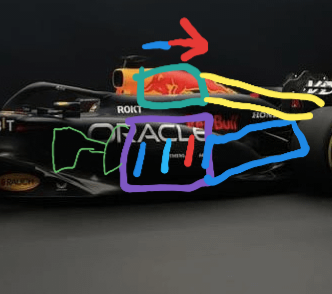
Let's say the engine is fed air from the vertical intakes and pretend the other sidepod intake is a dummy meant to throw teams off the scent.

To match other cars redbull would need a really efficient air to air intercooler on top of the engine.

For the engine intakes refer to @vorticism's post and diagram.
Image

Now excuse my poorly annotated drawing, the purple rectangle is the engine block, the small green lines represent the engine intake and the turbo compressor, the thick green line represents the air to air intercooler, the blue rectangle represents the transmission and the yellow represents the path the air would take after cooling the compressed air.

This can work but my question is with a limited budget why would they pursue this? The tradeoffs if not done properly are poor reliability, a high center of gravity, increased drag and more weight.

The weight and center of gravity are self explanatory. For the reliability part, refer to the arrow at the top and the three lines in the engine. That represents the fact the two cylinders at the front would always run the coolest while the rear two will run hotter because they are ingesting hotter air. This means that two of the six cylinders would be tuned to make less power because hotter air temperatures increase the risk of engine knocking. This also may make the engine suffer from more vibrations. We also should note that I didn't put in any oil coolers, engine coolers heck even the transmission cooler was omitted. All of this heat needs to be managed and yet they also need to prioritize cooling the intake air to make the most engine power. With this layout the rest of the coolers will come after the charge cooler which again won't do good for their temperatures. Good luck idling the car without overheating.


The next part is drag. Since drag is a function of speed, designers often increase the volume right after the intake to lower the air speed which would cut the drag. With this layout I am not sure if they have enough volume to play with in that area to pull off this trick. Again, think of how much they have to cool.


Lastly if it was feasible Mercedes would've gone with it to reduce the size of the sidepods at least for the w14 where they doubled down.

TLDR, it is possible, it can work but it isn't feasible.

Santozini
Santozini
5
Joined: 27 Feb 2017, 10:47

Re: Red Bull RB20

Post

vorticism wrote:
17 Feb 2024, 09:25
What’s that, anon? You didn’t know it’s it’s been legal to use two engine air intakes since 2014? I’m reasonably confident that Red Bull might been the first team to finally try it. I’ve illustrated the concept below.


https://pbs.twimg.com/media/GGhUSOlXAAA ... name=large
https://pbs.twimg.com/media/GGhYdQmWQAA ... me=900x900
https://pbs.twimg.com/media/GGhVfmCXgAA ... ame=medium
https://pbs.twimg.com/media/GGhXOaVWsAA ... name=large


The rule for engine air intakes does not specify any y-axis locations, only z and x. The same small free loophole zone that Ferrari exploited for their S-duct I propose is being used here as well, except as an engine intake rather than for entry into a duct. The vertical slots visible on the RB20 in photographs are located within the permitted zones of engine intake air; yes, even in that unusual location.

“But the air there! It is dirty!” you’ll say; but anon, do you not remember that the halo has been compromising clean flow the roll hoop inlets for many seasons now? The airflow may not be so disadvantageously noisy nor turbulent compared to halo wake. Combine that with the new shark-mouth/brimmed sidepod inlet present on RB20 which helps constrain and compile airflow through that region, while perhaps helpfully increasing pressure and stagnation in a way that could not be achieved ahead of a current F1 roll hoop inlet.

Also consider that such a thin cheese grater type of inlet will do well at eating the oncoming boundary layer present in this aerodynamically important area. The compressor will supply the two intake plenums with a constant source of manifold vacuum, and the combined effect of boundary layer thinning and increase in total mass flow could help the various floor edge functions.

With no engine air intake in the roll hoop, the roll hoop becomes exclusively used to feed centerline radiators. This could allow the sidepod inlets to be reduced in size. The Merc type pretzel shape roll hoop inlet I do not consider to be aerodynamically ideal due the that shapes involved; so why would RB bother with it? This was the detail that seemed most odd to me on RB20. If there is a greater mass of radiator core placed higher in the car, then they would need to take weight out of the roll hoop, and an A frame roll structure as in the center of the pretzel, provides that.

The regulation which permits engine air intakes across a rather large span:
5.15.1 With the exception of incidental leakage through joints or cooling ducts in the inlet system (either into or out of the system), all air entering the engine must enter the bodywork through a maximum of two inlets which are located on a single X plane between XC= -850 and XR= -500 and above Z=200.
Furthermore, any such inlets must be visible in their entirety when viewed from the front of the car without the driver seated in the car and with the secondary roll structure and any parts attached to it removed (see Article 12.4.2).
The original intent for this reg must have been to enable use of the main sidepod inlets as the air intake(s) in addition to feeding the radiators. I'm 90% sure I have the dimensions correctly interpreted, but I'd be happy to be proven wrong. I wouldn't normally go out so far on such a limb but what struck me was the coincidence of the rules seeming to permit an intake in the exact area. It was, for me, too much of a coincidence. Why not employ this on RB18 or RB19? Perhaps there was too much of a challenge packaging it, as those cars were said to have been over regulation weight.


https://twitter.com/athalkunni/status/1 ... 51068?s=20
Very interesting! Could these side intakes be responsible for the spaceship noise we could her on the Silverstone video? The way the air gets sucked into these intakes? Sounded almost like whistling, or a jet engine :shock:

User avatar
Holm86
247
Joined: 10 Feb 2010, 03:37
Location: Copenhagen, Denmark

Re: Red Bull RB20

Post

Santozini wrote:
19 Feb 2024, 12:39
vorticism wrote:
17 Feb 2024, 09:25
What’s that, anon? You didn’t know it’s it’s been legal to use two engine air intakes since 2014? I’m reasonably confident that Red Bull might been the first team to finally try it. I’ve illustrated the concept below.


https://pbs.twimg.com/media/GGhUSOlXAAA ... name=large
https://pbs.twimg.com/media/GGhYdQmWQAA ... me=900x900
https://pbs.twimg.com/media/GGhVfmCXgAA ... ame=medium
https://pbs.twimg.com/media/GGhXOaVWsAA ... name=large


The rule for engine air intakes does not specify any y-axis locations, only z and x. The same small free loophole zone that Ferrari exploited for their S-duct I propose is being used here as well, except as an engine intake rather than for entry into a duct. The vertical slots visible on the RB20 in photographs are located within the permitted zones of engine intake air; yes, even in that unusual location.

“But the air there! It is dirty!” you’ll say; but anon, do you not remember that the halo has been compromising clean flow the roll hoop inlets for many seasons now? The airflow may not be so disadvantageously noisy nor turbulent compared to halo wake. Combine that with the new shark-mouth/brimmed sidepod inlet present on RB20 which helps constrain and compile airflow through that region, while perhaps helpfully increasing pressure and stagnation in a way that could not be achieved ahead of a current F1 roll hoop inlet.

Also consider that such a thin cheese grater type of inlet will do well at eating the oncoming boundary layer present in this aerodynamically important area. The compressor will supply the two intake plenums with a constant source of manifold vacuum, and the combined effect of boundary layer thinning and increase in total mass flow could help the various floor edge functions.

With no engine air intake in the roll hoop, the roll hoop becomes exclusively used to feed centerline radiators. This could allow the sidepod inlets to be reduced in size. The Merc type pretzel shape roll hoop inlet I do not consider to be aerodynamically ideal due the that shapes involved; so why would RB bother with it? This was the detail that seemed most odd to me on RB20. If there is a greater mass of radiator core placed higher in the car, then they would need to take weight out of the roll hoop, and an A frame roll structure as in the center of the pretzel, provides that.

The regulation which permits engine air intakes across a rather large span:
5.15.1 With the exception of incidental leakage through joints or cooling ducts in the inlet system (either into or out of the system), all air entering the engine must enter the bodywork through a maximum of two inlets which are located on a single X plane between XC= -850 and XR= -500 and above Z=200.
Furthermore, any such inlets must be visible in their entirety when viewed from the front of the car without the driver seated in the car and with the secondary roll structure and any parts attached to it removed (see Article 12.4.2).
The original intent for this reg must have been to enable use of the main sidepod inlets as the air intake(s) in addition to feeding the radiators. I'm 90% sure I have the dimensions correctly interpreted, but I'd be happy to be proven wrong. I wouldn't normally go out so far on such a limb but what struck me was the coincidence of the rules seeming to permit an intake in the exact area. It was, for me, too much of a coincidence. Why not employ this on RB18 or RB19? Perhaps there was too much of a challenge packaging it, as those cars were said to have been over regulation weight.


https://twitter.com/athalkunni/status/1 ... 51068?s=20
Very interesting! Could these side intakes be responsible for the spaceship noise we could her on the Silverstone video? The way the air gets sucked into these intakes? Sounded almost like whistling, or a jet engine :shock:
That was the sound of a drone filming

Venturiation
Venturiation
98
Joined: 04 Jan 2023, 19:48

Re: Red Bull RB20

Post

organic wrote:
17 Feb 2024, 15:33
Venturiation wrote:
17 Feb 2024, 15:33
organic wrote:
17 Feb 2024, 15:31

Only based on one report. Some good sources contradict what the Autosport article writes.

Autosport may be interpreting 'Zeropod' differently to you or I might compared to a layperson. It's very easy for them to deploy the term zeropod and hook a bunch of clicks
This report is from Motorsport
Autosport and Motorsport are essentially the same thing... They have not been independent entities ever since Motorsport bought Autosport. For instance, if you go to motorsport.com photo archive it has the same photos as autosport, and Autosport articles use content from Motorsport and vice versa. It's no surprise that a Motorsport TR reporter will have the same info as Autosport

The car at the launch will not be the same as the Bahrain test and the car will receive an update at Japan but the reports of full on zeropods is I don't think accurate based on what I've heard. Essentially sensationalism
they were the ones that broke the W13 zeropods news weeks in advance


https://tr.motorsport.com/f1/news/merce ... r/8460474/

User avatar
organic
1055
Joined: 08 Jan 2022, 02:24
Location: Cambridge, UK

Re: Red Bull RB20

Post

I'm not trying to discredit Autosport. Just explaining the links between Autosport and Motorsport and why they have the same content

Regardless I don't believe zeropods will come. Just a buzzword

Martin Keene
Martin Keene
7
Joined: 11 May 2010, 09:02

Re: Red Bull RB20

Post

I agree. If you watch any of the Kyle Engineers video's about this generation of cars, the key to unlocking the performance appears to be generating an area of high pressure above the front of the floor, under the sidepod undercut. That also helps manage the tyre wake by pushing the turbulent air outboard.

Any form of minimalist sidepod, zeropod is ridiculous name because they are still side pods, is going to remove the ability to generate that area of high pressure.

AR3-GP
AR3-GP
365
Joined: 06 Jul 2021, 01:22

Re: Red Bull RB20

Post

Venturiation wrote:
19 Feb 2024, 13:55
organic wrote:
17 Feb 2024, 15:33
Venturiation wrote:
17 Feb 2024, 15:33


This report is from Motorsport
Autosport and Motorsport are essentially the same thing... They have not been independent entities ever since Motorsport bought Autosport. For instance, if you go to motorsport.com photo archive it has the same photos as autosport, and Autosport articles use content from Motorsport and vice versa. It's no surprise that a Motorsport TR reporter will have the same info as Autosport

The car at the launch will not be the same as the Bahrain test and the car will receive an update at Japan but the reports of full on zeropods is I don't think accurate based on what I've heard. Essentially sensationalism
they were the ones that broke the W13 zeropods news weeks in advance


https://tr.motorsport.com/f1/news/merce ... r/8460474/
News outlets have both hits and misses. This is true.
A lion must kill its prey.

FNTC
FNTC
7
Joined: 03 Nov 2023, 21:27

Re: Red Bull RB20

Post

Bernie Collins on the RB20 from around 29:30:


"I think maybe years in F1 have made me suspicious, so let's see the car that rocks out on day one of Bahrain, because I'm not sure it's going to be that car. Like, this could just be a "oh, we're just having a joke". So I'm highly suspicious. But let's see. If they do rock out with that car, then you know, it's a brave, brave move."
More in the video.