Red Bull RB20

A place to discuss the characteristics of the cars in Formula One, both current as well as historical. Laptimes, driver worshipping and team chatter do not belong here.
skwdenyer
skwdenyer
13
Joined: 17 May 2010, 00:00

Re: Red Bull RB20

Post

The key to understanding this design IMHO is to stop thinking of air “feeding” or “flowing in” or whatever. That’s where almost everybody continually runs behind the curve.

The hallmark of the Newey cars is efficiency - so much downforce, yet so much top speed, etc.

Each molecule of air must - as it were - know where it is going before it gets there. It is not enough just to steer it in the moment - because ordinary perturbations will disrupt and destroy the effect.

So we should start to analyse this design at the exits, not the entrances. Where is the air to end up, and in what condition?

Those vertical sidepod slots, for instance, are brilliant flow conditioners. Amongst other things they’re performing the old Murray McLaren F1 fan trick of “stripping away the boundary layer,” leaving much better-conditioned flows.
But how to stop those slot flows stalling? Well, where would they be useful, and how much energy is required to make them useful?

Those halo inlets likewise are a great way to “suck away” some nasty flow structures, letting the engine provide the heat to energise them (the bend in the duct really doesn’t matter for that), and leaving a cleaner flow down the cannons and over the rear.

Anyhow, just my two cents :)

mzso
mzso
65
Joined: 05 Apr 2014, 14:52

Re: Red Bull RB20

Post

matteosc wrote:
02 Mar 2024, 16:23
AR3-GP wrote:
01 Mar 2024, 17:48
Venturiation wrote:
01 Mar 2024, 17:40
What is the red cover on the rear floor
Rb covers the vertical inlet, but Ferrari does not.
Ferrari's are not for cooling (presumably), but only for the S-duct. This would confirm that Red Bull's vertical inlets are for cooling purposes.
So what do they do? Blow it with a PC fan? Or why is there coiled electric wire there?
Also, how did they cool the main inlet, I don't think I saw it yet. Right here it only seems to be plugged.

Farnborough
Farnborough
99
Joined: 18 Mar 2023, 14:15

Re: Red Bull RB20

Post

skwdenyer wrote:
02 Mar 2024, 23:40
The key to understanding this design IMHO is to stop thinking of air “feeding” or “flowing in” or whatever. That’s where almost everybody continually runs behind the curve.

The hallmark of the Newey cars is efficiency - so much downforce, yet so much top speed, etc.

Each molecule of air must - as it were - know where it is going before it gets there. It is not enough just to steer it in the moment - because ordinary perturbations will disrupt and destroy the effect.

So we should start to analyse this design at the exits, not the entrances. Where is the air to end up, and in what condition?

Those vertical sidepod slots, for instance, are brilliant flow conditioners. Amongst other things they’re performing the old Murray McLaren F1 fan trick of “stripping away the boundary layer,” leaving much better-conditioned flows.
But how to stop those slot flows stalling? Well, where would they be useful, and how much energy is required to make them useful?

Those halo inlets likewise are a great way to “suck away” some nasty flow structures, letting the engine provide the heat to energise them (the bend in the duct really doesn’t matter for that), and leaving a cleaner flow down the cannons and over the rear.

Anyhow, just my two cents :)
Those tubes are not continuous and separated front and rear. Theres a "blocking" plate just after the outside exit gills, leaving the front section discreet with a heat exchanger in the flow to simply exit above sidepod.
The rear section is channelled directly from exit flow rising path from primary sidepod heat exchangers to flow out the rear exit either side of exhaust.

Pictures further up the thread with covers off showing internal flow path etc.

venkyhere
venkyhere
14
Joined: 10 Feb 2024, 06:17

Re: Red Bull RB20

Post

Farnborough wrote:
03 Mar 2024, 22:15
Those tubes are not continuous and separated front and rear. Theres a "blocking" plate just after the outside exit gills, leaving the front section discreet with a heat exchanger in the flow to simply exit above sidepod.
Yes, this is very clear from pics
Farnborough wrote:
03 Mar 2024, 22:15
The rear section is channelled directly from exit flow rising path from primary sidepod heat exchangers to flow out the rear exit either side of exhaust.

Pictures further up the thread with covers off showing internal flow path etc.
This was unclear to me. So if this is how the V-arranged heat exchangers in the sidepod have their hot air exiting the car, then what does the 'sidepod cannon exit' at the rear of the sidepods, beneath the "RedBull" and "Honda" stickers towards the coke bottle area, do ? Where do those two exits draw their hot air from ?

Farnborough
Farnborough
99
Joined: 18 Mar 2023, 14:15

Re: Red Bull RB20

Post

Unsure if I've worded my description clearly .... it looks like all of the primary air cooling outflow exits via "cannon" exit located either side of exhaust outlet, there doesn't appear much in the way of additional venting at rear of sidepod other than that route.

Detailed picture, with covers removed, are all usually at oblique angle ftom the front 3/4 view, naturally as it's only removed when in their box. Concise views not yet available otherwise in public domain. So a little difficult to fully form accurate opinion.

There's that small outlet down by the front entry point of rear suspension arm to facilitate that mounting, on previous iteration of chassis too, but not a substantial volume in flow to be anywhere near total required. There's now a small water slide surface leading down through there, perhaps the small outlet facilitates keeping that flow attached to improve effectiveness at that point.

The cannon exit though, with the exhaust being a dominant exit of energy in it's rules proscribed location, LOOKS like it could be of value in coanda ? implementation to pull that sidepod exit volume into its sphere of influence and raise the extraction performance of cooling system as whole.
The exhaust was obviously moved to negate its use down infront of and between the rear wheels, the energy is still there (supposedly neutral by design direction of rules) but may be playing more of a part in this car now by that exit placing.
In other words, IF the extraction process (bypass flow jet engines do something similar, although enclosed in casing substantially) then the whole system efficiency should be raised, to also facilitate smaller intake size without loss occurring.

Effective in the first view we've had racing so far, more adventurous than many were expecting too. There's certainly interesting details in there.
Last edited by Farnborough on 04 Mar 2024, 09:21, edited 1 time in total.

Farnborough
Farnborough
99
Joined: 18 Mar 2023, 14:15

Re: Red Bull RB20

Post

An exhaust effect like that I've mentioned in previous post is "core jet efflux" with a variance of bypass ratio dependent on application.

Obviously the "coanda" description is wrong in this application :D

Essentially "dragging" the air column surrounding the core energy projection to improve thrust/extraction of total volume and its effectiveness.

venkyhere
venkyhere
14
Joined: 10 Feb 2024, 06:17

Re: Red Bull RB20

Post

@Farnborough,
Thanks for your replies.. to further dispel any doubts, can we use the diagram below, as reference ?
Image


The mappings I am able to do, from inlets to outlets are :
inlet# --> component --> exit#

4 --> IC engine ---> exhaust
5 --> radiator (unknown) --> ?
3 --> radiator (unknown) --> 3
1 --> water radiator (sidepod) --> ?
1 --> air to air IC (sidepod) --> ?
2 --> <what thing> --> ?

What is the <what thing>
How do air exits 1,2,4,5,6 get mapped to each of the ? above

Farnborough
Farnborough
99
Joined: 18 Mar 2023, 14:15

Re: Red Bull RB20

Post

Gills in "elephant trunk valley" appear to be exit of centreline cooling matrix that can be seen above engine directly when covers are off.
No images of inside the cover itself to see if there's directional path incorporated.

The whole strategy appears to separate each cooling function with semi discreet intake and outflow, likely by different cooling gradient ? for that dedicated function.
The sidepod main cooling function V matrix being of a consolidated group.

If these various elements can be "shuttered" individually, then that particular cooling circuit modulation may bring efficiency and size gains in being more specific to that duty cycle as opposed to being somewhat included within another profile of use.

Unsure if its generally realised with most race cars the big difference in cooling facilities when compared to most road vehicles. As a comparison, road vehicle being installed with maximised cooling capability, then modulated with thermostatic valves for liquid flow, airflow (active shuttered radiators) electric fans and temperature sensitive viscous coupled fan torque, a whole conglomeration of tools to first bring heat up fast, then maintaining at target temperature for continuous performance.

Race on the other hand, try to carry minimum cooling facilities, no thermostatic control, along with pure dependance on calculation / projection to cope with expected ambient conditions. Once set from exit venting etc, thats it for the race, they then have to work round what comes, likely by reducing PU, shifting to run in cleaner air etc.

These discreet exits with little to no interrelationship may allow a more tailored setup refinement to avoid drag and specifically prevent conflation in having to make broad choices to open general vents instead of now tweaking individual in reaction to circumstances.

maxxer
maxxer
1
Joined: 13 May 2013, 12:01

Re: Red Bull RB20

Post

venkyhere wrote:
04 Mar 2024, 12:18
@Farnborough,
Thanks for your replies.. to further dispel any doubts, can we use the diagram below, as reference ?
https://i.imgur.com/Y2UIBff.png


The mappings I am able to do, from inlets to outlets are :
inlet# --> component --> exit#

4 --> IC engine ---> exhaust
5 --> radiator (unknown) --> ?
3 --> radiator (unknown) --> 3
1 --> water radiator (sidepod) --> ?
1 --> air to air IC (sidepod) --> ?
2 --> <what thing> --> ?

What is the <what thing>
How do air exits 1,2,4,5,6 get mapped to each of the ? above
Inlet 2 must be going down quick and cool the battery i think

User avatar
vorticism
323
Joined: 01 Mar 2022, 20:20

Re: Red Bull RB20

Post

Could be, or it could merge with the main radiator inlet plenum. Photos of the area are still too blurry at the interface for me to confirm. That said, I reiterate that the best S-duct would be one driven by a high flow turbomachine assisted combustion heated air pump.
Last edited by vorticism on 05 Mar 2024, 20:25, edited 1 time in total.
𓄀

Henk_v
Henk_v
86
Joined: 24 Feb 2022, 13:41

Re: Red Bull RB20

Post

My2 ct

4 --> Engine compartment & ICU ---> ICU -> 6, Engine compartment -> 2, outlet to suck the hot ambient air out
5 --> Centerline cooling ---> 4
3 --> radiator (unknown) --> 3
1 --> water radiator (sidepod) --> 6 & 5
1 --> air to air IC (sidepod) --> 6 & 5
2 --> <what thing> --> 4b, behind the gills are massive outlets

Farnborough
Farnborough
99
Joined: 18 Mar 2023, 14:15

Re: Red Bull RB20

Post

Difficult to determine with any accuracy the destination of inlet #2 we obviously know the location of both this and the battery's installation, but no idea whether linked or used for that function.

Demand profile of battery cooling may be different from other function by enough to facilitate dedicated and with little overall control/restriction needed to make separation an obvious choice. Less critical in sensitivity to ambient in other words. A possibility, but needing more stripped images to establish, unlikely to be got easily I'd guess though, and a differentiator the other team would love to see no doubt.

venkyhere
venkyhere
14
Joined: 10 Feb 2024, 06:17

Re: Red Bull RB20

Post

Thanks @Farnborough & @Henk_v
I have cleaned up the image :
Image

Based on conjecture so far ,

inlet# --> component --> outlet#
4 --> ICU --> 1 (exhaust)
4---> Engine compartment --> 6 (main) & 2 (outlet to suck the hot ambient air out)
5 --> Centerline cooling ---> 4
3 --> radiator (unknown) --> 3
1 --> water radiator (sidepod) --> 6 & 5
1 --> air to air IC (sidepod) --> 6 & 5
2 --> <what thing> --> 4b, behind the gills are massive outlets

I wonder whether exit #4b and exit #2 in the above paths, must be swapped.

Total inlet "sets" = 4+5(pair)+1(pair)+2(pair)+3(pair) = 9
Total outlet "sets" = 1+6+2(pair)+4(pair)+4b(pair)+5(pair)+3(pair) = 12
Based on circuit requirements the total number of each can change.

venkyhere
venkyhere
14
Joined: 10 Feb 2024, 06:17

Re: Red Bull RB20

Post

The man himself has spoken about RB20

https://www.planetf1.com/news/adrian-ne ... -dismissed
I mean, the underlying architecture of the car is the third generation evolution of what started as RB18.

Where we carry everything, apart from the radiators, they’ve changed, but apart from that, the layout of the front suspension, the rear suspension, the gearbox, casing, et cetera, it’s a third evolution of RB18.

The bits that are visible, and they’ve obviously caused quite a lot of attention, obviously, we’re pursuing aerodynamic gains there, but the visual change is actually much, much larger than the performance change you get from that and there are other much more subtle bits, that people haven’t noticed, that are probably responsible for a bigger gain.

That’s what we’ve tried to achieve, is a car that is reasonably well suited to all circuits.

I think, typically, last year are the circuits that we had less of an advantage on were the maximum downforce street tracks.

Singapore, obviously, we made famously made a bit of a mess of, underperformed to what we could have achieved – I think we could have certainly achieved podiums there had we got our act together a bit better.

But it certainly is true to say that those circuits are the ones that we probably have less advantage on, but as long as we’re not disastrous on them, then maybe that’s good enough.

CaribouBread
CaribouBread
101
Joined: 29 Mar 2022, 08:37

Re: Red Bull RB20

Post

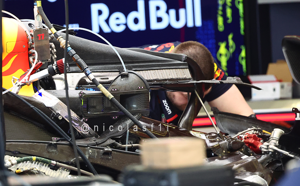
Image by Nicolas Carpentiers
Image

I won't even call that the centerline cooling, that's top level cooling, Guessing the tube is another cooling duct running to some sort of cooler on top of the gearbox? What could those blue arrow, cockpit inlet rads be for?