Mercedes W15

A place to discuss the characteristics of the cars in Formula One, both current as well as historical. Laptimes, driver worshipping and team chatter do not belong here.
User avatar
atanatizante
115
Joined: 10 Mar 2011, 15:33

Re: Mercedes W15

Post

Farnborough wrote:
15 Jul 2024, 14:20
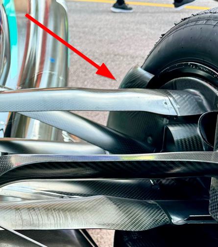
Brake duct intake is the shroud running forward around the tyre sidewall curtailing at the edge where wall meets tread area.

They use it just one sided with the other being the tyre itself.
I thank you, dear Sir!
Do you mean this piece of bent carbon fiber?

Image
"I don`t have all the answers. Try Google!"
Jesus

User avatar
atanatizante
115
Joined: 10 Mar 2011, 15:33

Re: Mercedes W15

Post

Holm86 wrote:
15 Jul 2024, 15:32
To me it looks a bit like this variable damper
https://www.rtri.or.jp/eng/rd/seika/200 ... v01_f2.jpg

Not sure if such a system would be legal or seen as active suspension

https://www.rtri.or.jp/eng/rd/seika/200 ... e_E01.html
An active suspension is hydraulically controlled by a computer hence it`s not allowed so they need to rely on a passive suspension acting like an active one ...
"I don`t have all the answers. Try Google!"
Jesus

Farnborough
Farnborough
99
Joined: 18 Mar 2023, 14:15

Re: Mercedes W15

Post

atanatizante wrote:
15 Jul 2024, 17:47
Farnborough wrote:
15 Jul 2024, 14:20
Brake duct intake is the shroud running forward around the tyre sidewall curtailing at the edge where wall meets tread area.

They use it just one sided with the other being the tyre itself.
I thank you, dear Sir!
Do you mean this piece of bent carbon fiber?

https://postimages.org/

Yes, that's it.

Can also clean up the airflow hitting front facing surface of tire as it collects lateral flow too, this to prevent that tumbling around inner face to further disturb general flow through that area.

Fairly high energy to pressurise brake duct volume.

Farnborough
Farnborough
99
Joined: 18 Mar 2023, 14:15

Re: Mercedes W15

Post

atanatizante wrote:
15 Jul 2024, 17:51
Holm86 wrote:
15 Jul 2024, 15:32
To me it looks a bit like this variable damper
https://www.rtri.or.jp/eng/rd/seika/200 ... v01_f2.jpg

Not sure if such a system would be legal or seen as active suspension

https://www.rtri.or.jp/eng/rd/seika/200 ... e_E01.html
An active suspension is hydraulically controlled by a computer hence it`s not allowed so they need to rely on a passive suspension acting like an active one ...
Just "conventional" damper can be specified with many different characteristics

https://www.penskeshocks.com/blog/linea ... -use-cases

Then depends where they are placed.

Hoffman900
Hoffman900
210
Joined: 13 Oct 2019, 03:02

Re: Mercedes W15

Post

RB and a few other teams are using Multimatic DSSV dampers:
https://www.multimatic.com/motorsports/ ... g-dampers/

not active per-se, but they’re pretty advanced.

User avatar
atanatizante
115
Joined: 10 Mar 2011, 15:33

Re: Mercedes W15

Post

Farnborough wrote:
15 Jul 2024, 18:00
atanatizante wrote:
15 Jul 2024, 17:47
Farnborough wrote:
15 Jul 2024, 14:20
Brake duct intake is the shroud running forward around the tyre sidewall curtailing at the edge where wall meets tread area.

They use it just one sided with the other being the tyre itself.
I thank you, dear Sir!
Do you mean this piece of bent carbon fiber?

https://postimages.org/

Yes, that's it.

Can also clean up the airflow hitting front facing surface of tire as it collects lateral flow too, this to prevent that tumbling around inner face to further disturb general flow through that area.

Fairly high energy to pressurise brake duct volume.
What are your thoughts about the brake air exhaust trajectory?
Could be that it`s strategically placed near the rear wing endplate? And the reason/reasons for doing this could be to diminish the bounder layer or just to induce a low pressure both on the beam wing and further to the diffuser?
"I don`t have all the answers. Try Google!"
Jesus

Farnborough
Farnborough
99
Joined: 18 Mar 2023, 14:15

Re: Mercedes W15

Post

atanatizante wrote:
15 Jul 2024, 18:46
Farnborough wrote:
15 Jul 2024, 18:00
atanatizante wrote:
15 Jul 2024, 17:47


I thank you, dear Sir!
Do you mean this piece of bent carbon fiber?

https://postimages.org/

Yes, that's it.

Can also clean up the airflow hitting front facing surface of tire as it collects lateral flow too, this to prevent that tumbling around inner face to further disturb general flow through that area.

Fairly high energy to pressurise brake duct volume.
What are your thoughts about the brake air exhaust trajectory?
Could be that it`s strategically placed near the rear wing endplate? And the reason/reasons for doing this could be to diminish the bounder layer or just to induce a low pressure both on the beam wing and further to the diffuser?
Yes there's effect, but exactly what you'd probably need fairly detailed access to their research to be conclusive.

The current regs prohibited airflow exit through front of wheel with std "hub" covers, meaning all air management has to be rear face.

The ducts must fulfill PRIMARY function as cooling device, but will assuredly be placed for best air management in relation to other component, likely stretching that interpretation as far as realistic within the rules. These having the potential to impinge on rules not allowing "movable" aerodynamic surfaces. So, tightly regulated, but with potential to direct exit flow within regulations. Believe that r&d time on cooling structures are not within aero research restrictions too, possibly :D

Same with suspension "legs" not effectively allowed to generate load through surface, but careful placement may provide significant benefits in over flowall strategy without breaching regulation.
Henk_v
Henk_v
86
Joined: 24 Feb 2022, 13:41

Re: Mercedes W15

Post

As the brake air is fed through a labyrinth of ducts, I'd bet the exit velocity of the air is far lower than the air over the car. You can't "energise" anything. I think it is the other way around. Air passing around the car is used to extract air from the exit duct to reduce the frontal surface of the intake .

Farnborough
Farnborough
99
Joined: 18 Mar 2023, 14:15

Re: Mercedes W15

Post

Henk_v wrote:
15 Jul 2024, 19:25
As the brake air is fed through a labyrinth of ducts, I'd bet the exit velocity of the air is far lower than the air over the car. You can't "energise" anything. I think it is the other way around. Air passing around the car is used to extract air from the exit duct to reduce the frontal surface of the intake .
To which bit are you referring ? Was anything claimed to be energised, or have I missed something?

The exit duct obviously has flow out of it, as you'd, expect.

But that structure also has external forn that can be advantageous in it's placement to flow strategy the designers are after.

Farnborough
Farnborough
99
Joined: 18 Mar 2023, 14:15

Re: Mercedes W15

Post

Hoffman900 wrote:
15 Jul 2024, 18:21
RB and a few other teams are using Multimatic DSSV dampers:
https://www.multimatic.com/motorsports/ ... g-dampers/

not active per-se, but they’re pretty advanced.
Interesting and well explained overview here https://www.caranddriver.com/news/a1534 ... explained/

User avatar
PlatinumZealot
559
Joined: 12 Jun 2008, 03:45

Re: Mercedes W15

Post

Hoffman900 wrote:
15 Jul 2024, 18:21
RB and a few other teams are using Multimatic DSSV dampers:
https://www.multimatic.com/motorsports/ ... g-dampers/

not active per-se, but they’re pretty advanced.
I think the formula 1 teams create extensions piping that go to passive hydraulic "brain blocks" to force open certain valving inside these advanced dampers at different accelerations and atittudes of the car.

The dampers probably come with hydraulic inputs and outputs that can be piloted by these other passive mechanical sensors elsewhere on the car.
🖐️✌️☝️👀👌✍️🐎🏆🙏

Racing Green in 2028

User avatar
PlatinumZealot
559
Joined: 12 Jun 2008, 03:45

Re: Mercedes W15

Post

Farnborough wrote:
15 Jul 2024, 19:38
Hoffman900 wrote:
15 Jul 2024, 18:21
RB and a few other teams are using Multimatic DSSV dampers:
https://www.multimatic.com/motorsports/ ... g-dampers/

not active per-se, but they’re pretty advanced.
Interesting and well explained overview here https://www.caranddriver.com/news/a1534 ... explained/
Great article.
🖐️✌️☝️👀👌✍️🐎🏆🙏

Racing Green in 2028

Farnborough
Farnborough
99
Joined: 18 Mar 2023, 14:15

Re: Mercedes W15

Post

PlatinumZealot wrote:
15 Jul 2024, 20:37
Hoffman900 wrote:
15 Jul 2024, 18:21
RB and a few other teams are using Multimatic DSSV dampers:
https://www.multimatic.com/motorsports/ ... g-dampers/

not active per-se, but they’re pretty advanced.
I think the formula 1 teams create extensions piping that go to passive hydraulic "brain blocks" to force open certain valving inside these advanced dampers at different accelerations and atittudes of the car.

The dampers probably come with hydraulic inputs and outputs that can be piloted by these other passive mechanical sensors elsewhere on the car.
Is that pure speculation ? Or some internal reporting that offers the information ?

As I understand it, the regulations specifically prohibit interlinked hardware in that description.

User avatar
PlatinumZealot
559
Joined: 12 Jun 2008, 03:45

Re: Mercedes W15

Post

Farnborough wrote:
15 Jul 2024, 20:53
PlatinumZealot wrote:
15 Jul 2024, 20:37
Hoffman900 wrote:
15 Jul 2024, 18:21
RB and a few other teams are using Multimatic DSSV dampers:
https://www.multimatic.com/motorsports/ ... g-dampers/

not active per-se, but they’re pretty advanced.
I think the formula 1 teams create extensions piping that go to passive hydraulic "brain blocks" to force open certain valving inside these advanced dampers at different accelerations and atittudes of the car.

The dampers probably come with hydraulic inputs and outputs that can be piloted by these other passive mechanical sensors elsewhere on the car.
Is that pure speculation ? Or some internal reporting that offers the information ?

As I understand it, the regulations specifically prohibit interlinked hardware in that description.
Only front to rear interlinking is banned IIRC.

Even within that there are loop holes. You could use quantum entanglement to link the front and the rear if you wanted, and the FIA would never find out.
🖐️✌️☝️👀👌✍️🐎🏆🙏

Racing Green in 2028

zioture
zioture
548
Joined: 12 Feb 2013, 12:46
Location: Italy

Re: Mercedes W15

Post

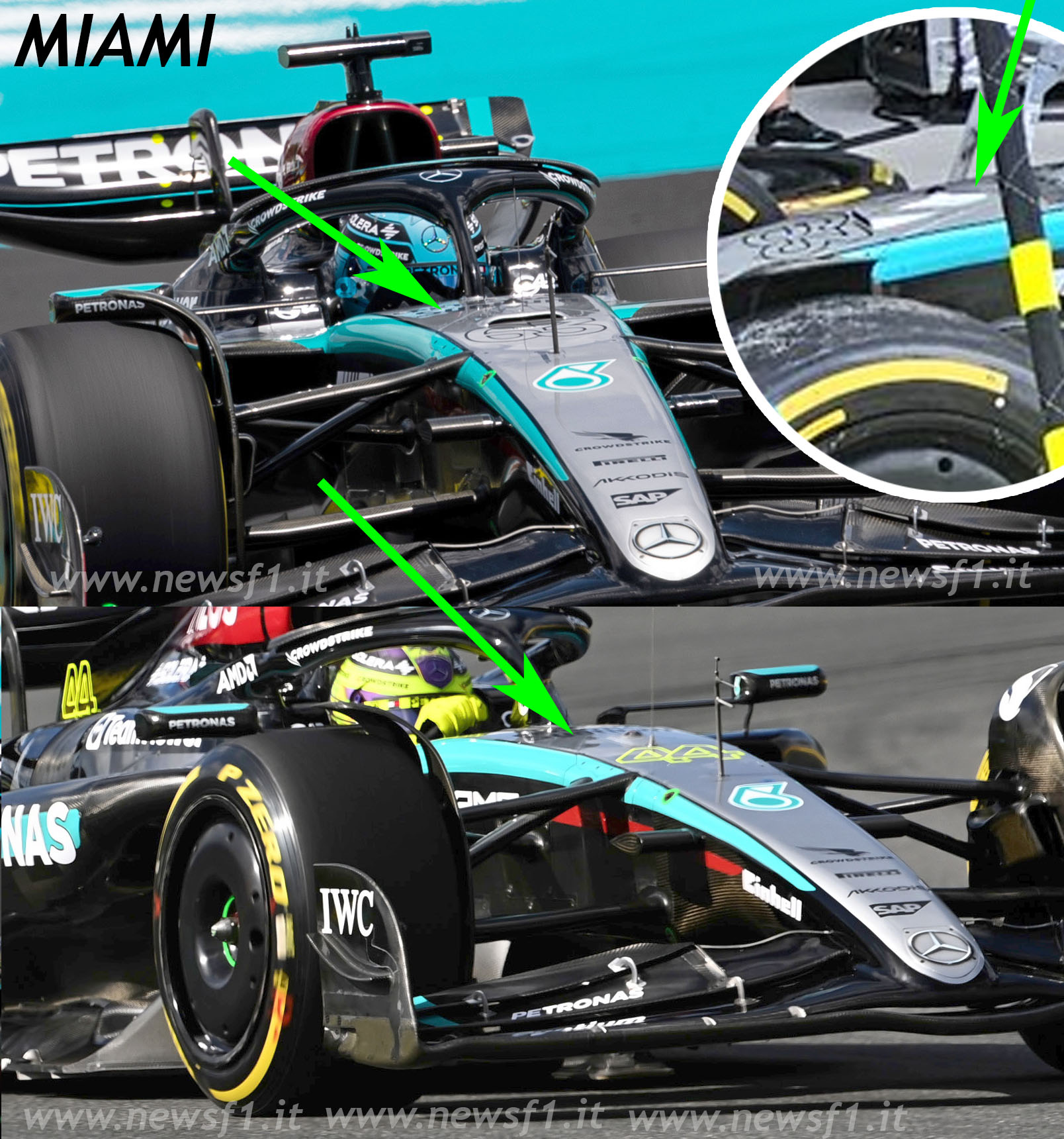
Look at this picture, Mercedes in my opinion had already modified the third elemeno since Miami, look at the cover has yes an air intake but also a vertical bulge just to accommodate the third suspension element . THE strange thing is that they didn't use this air intake to cool Hamilton's macchian, and they didn't use this air intake at Imola and Monte Carlo... tracks where instead Red bull used the 2 small air intakes.


Image