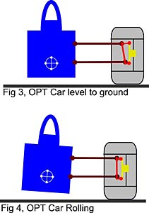
I made a simple CAD model today to see how the suspension actually behaves.
Seems like I made one mistake on my last post:
bump: (both wheels up): both wheels gets positive chamber
In fact they get negative chamber when both wheels go up and positive when they go down. Hm I would like them to change towards positive more.
I also noticed that during roll they don't stay 100% parallel but almost.
Also:
left wheel up (single wheel bump): right wheel gets positive chamber
and left wheel gets towards negative chamber.
In fact when I write positive or negative chamber it doesn't mean that there actually is positive or negative chamber I just want to point out that it goes into this direction. It depends what chamber you had on neutral position. When you have zero on neutral you will see the above.
these 1:10 scale cars have a quite high CoG... and a very low RC (4cm below the CoG, or more)... and with their 200mm width limit they are quite sensetive on high traction tracks, they often suffer from traction roll.
So trowing your concerns about roll out of the window is, in my opinion, not the way to go.
Yea 4cm seems to be a lot for such a small car. What do you think actually is the problem with the cars rolling? Maybe the problem is just that your tires get into a bad chamber angle when your car body rolls and therefore they loose contact patch. This problem should be fixed with this design because tires almost stay parallel. On the other hand I think it helps when your inside tire gets slightly positive during roll. Why not just rise your RC on your normal suspension to get some anti-geometry.
(hmm 747 understands german, I am kinda surprised by this)


