Hi folks!
Finaly an update:
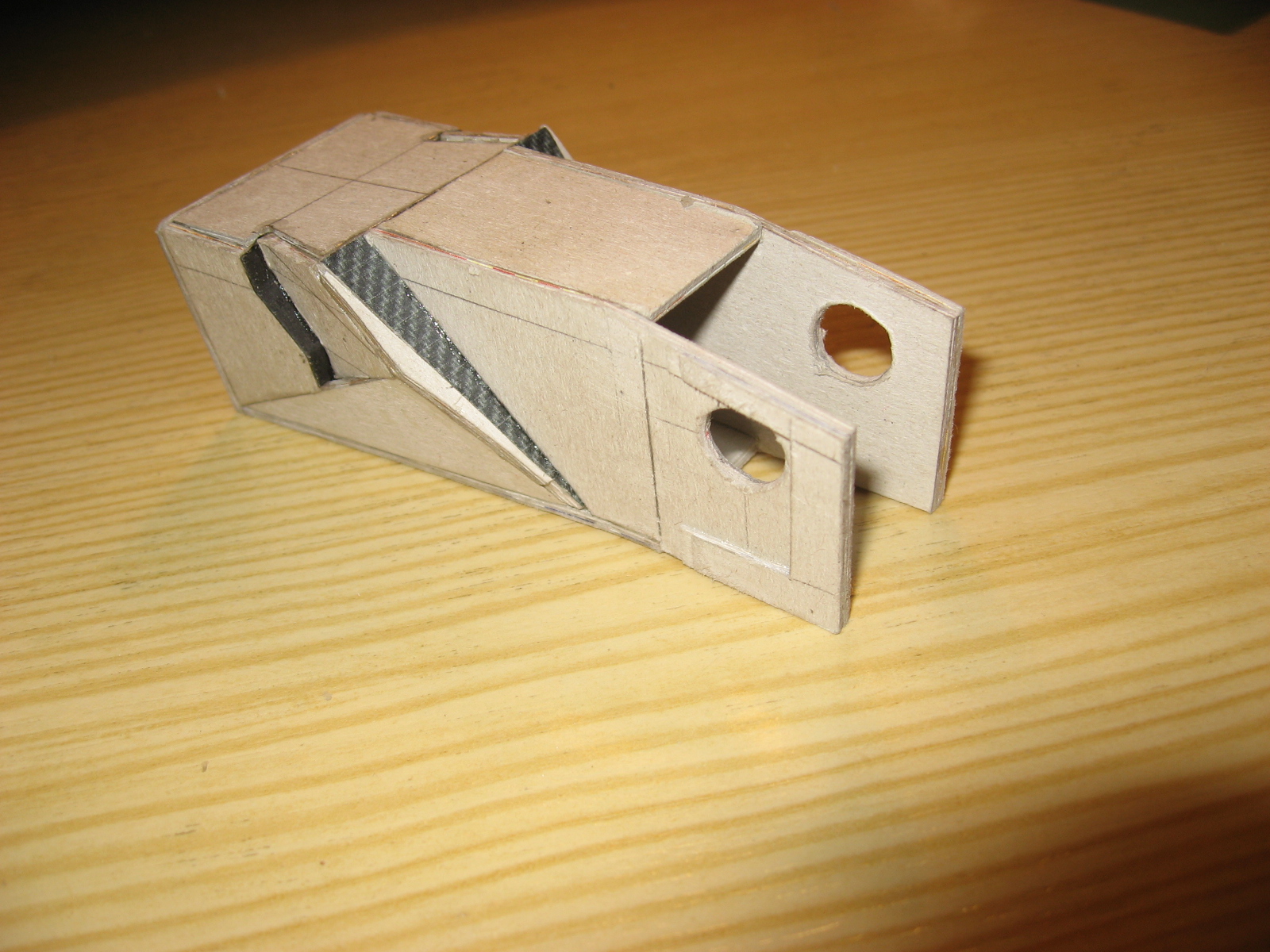
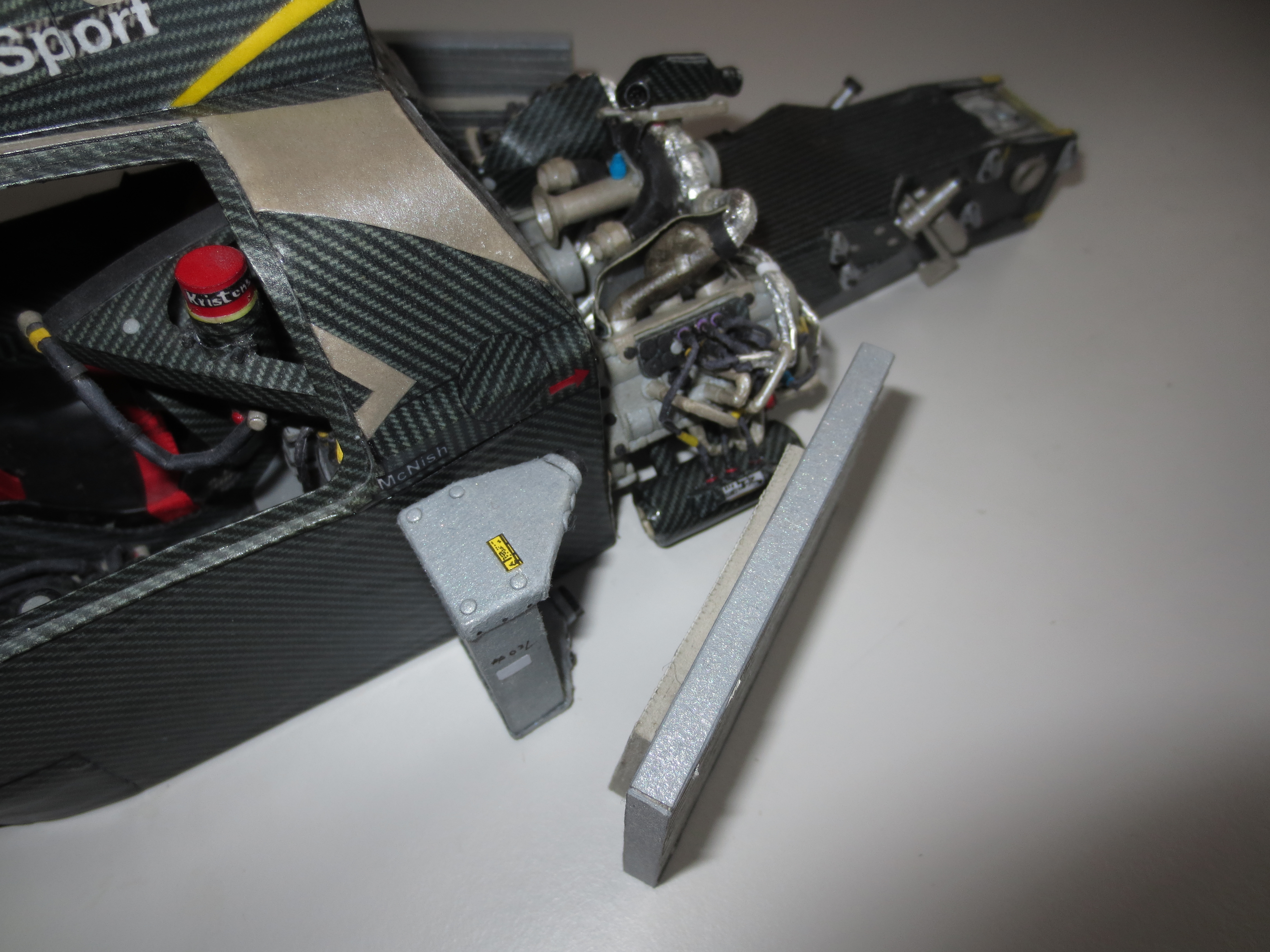
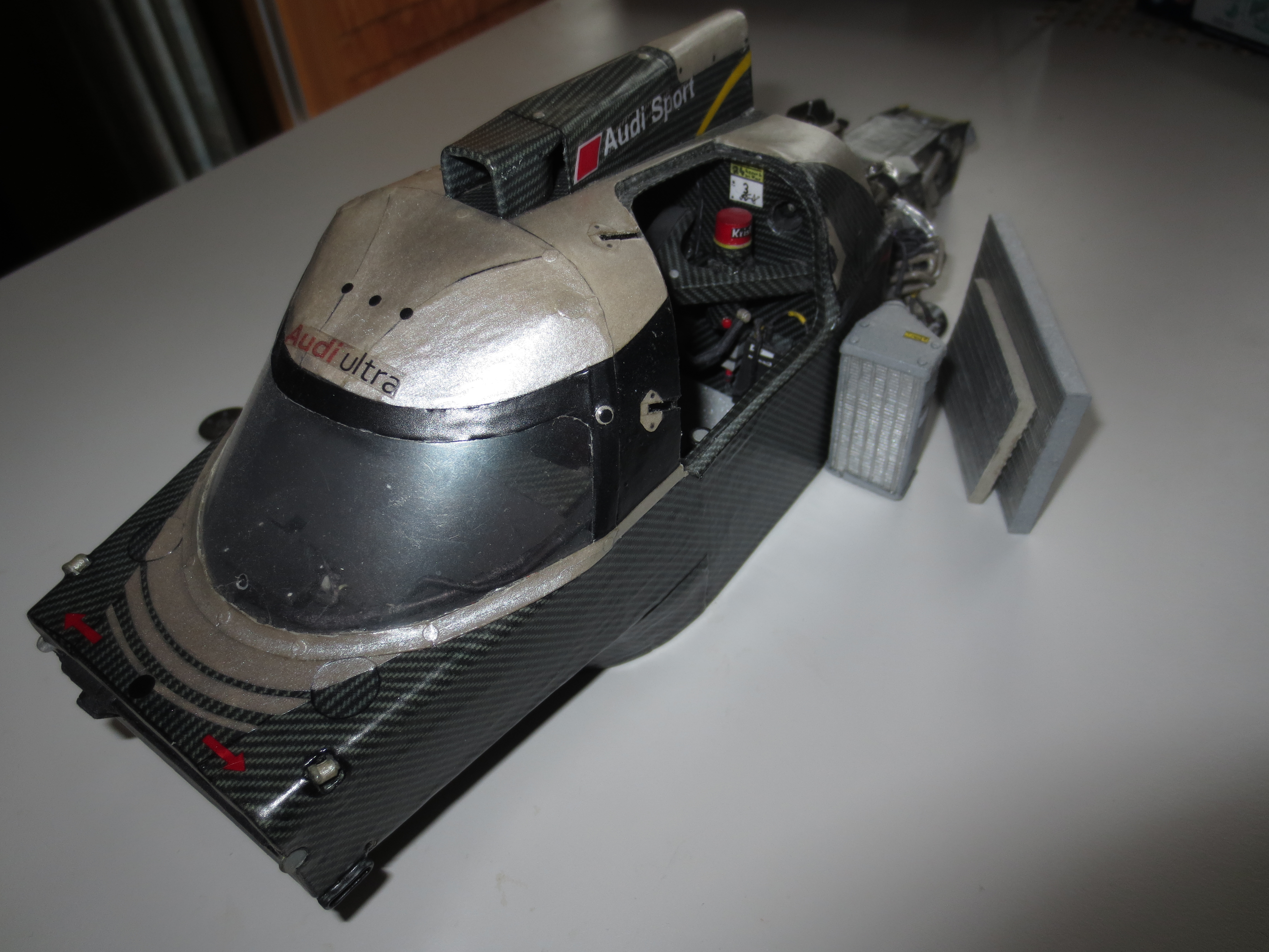
After I was yammering so hard about my big mistakes, I was able to solve at least one of them. In fact, I was able to realize the cutout in the monocoque for the oil tank. Even if it demanded all my skills and patience, the current solution is quite good (what means not perfect). After I wasn't able to get through the rear wall of the monocoque with a hammer and a scalpel (a broken blade), it needed an Aluminium-saw to get it done. I was impressed by myself how extremly hard and resistant the wall/bulkhead was.
With a little help, I also know now, how the oil is cooled. A dedicated engineer of
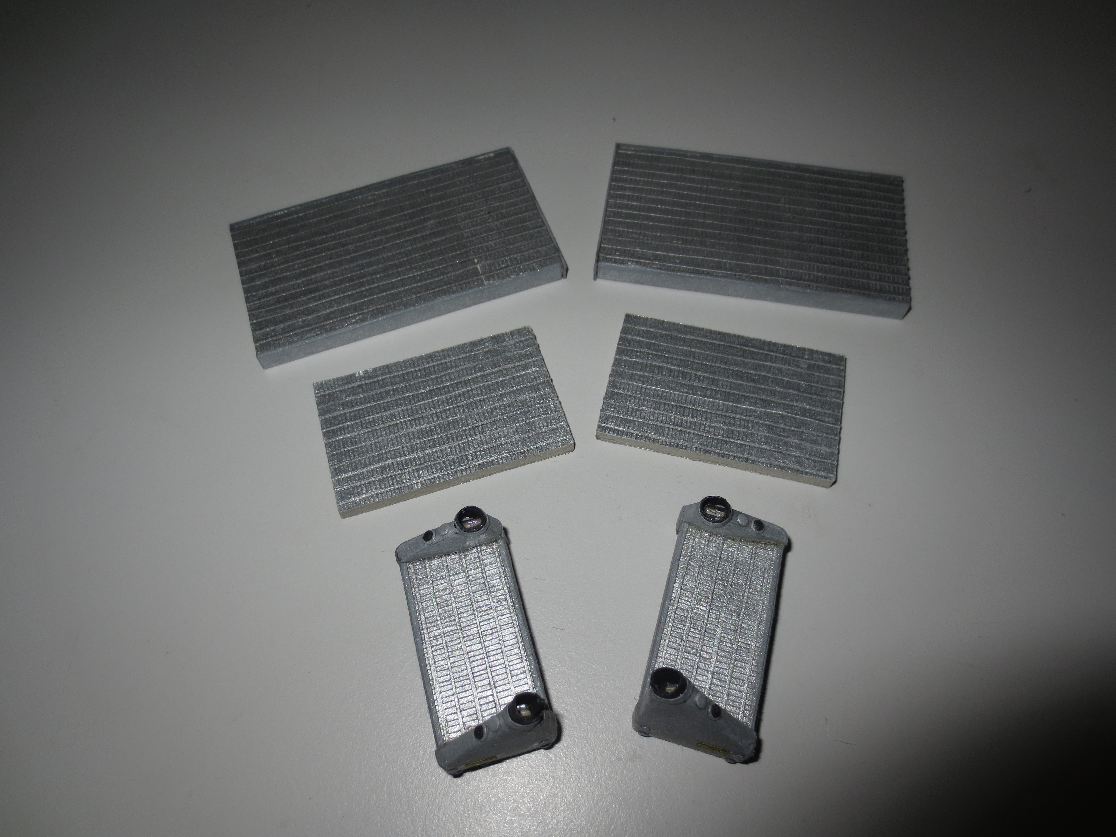
Cummins Turbos enlighted me. As he said, it's very common in aerospace to cool the oil down by the fuel. That sounds very plausible to me, because the oil tank (at the front of the engine) is more or less surrounded by fuel, only apart by a few milimetres of carbon fibre and a bit rubber from the safety fuel tank. The fuel itself is cooled by radiators which are placed alongside the water radiators. As I wrote in a post before, the fuel has to be cooled down because a part of the compressed fuel from the common rail system flews back into the tank. The compressed fuel has a temperature of about 140°C (Wikipedia).
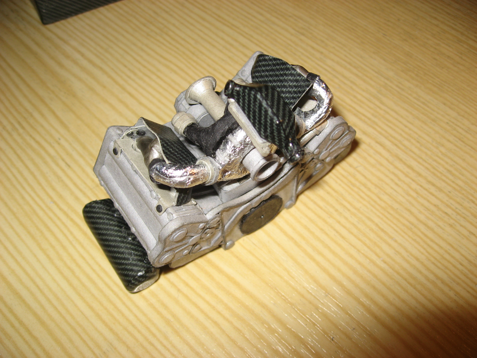
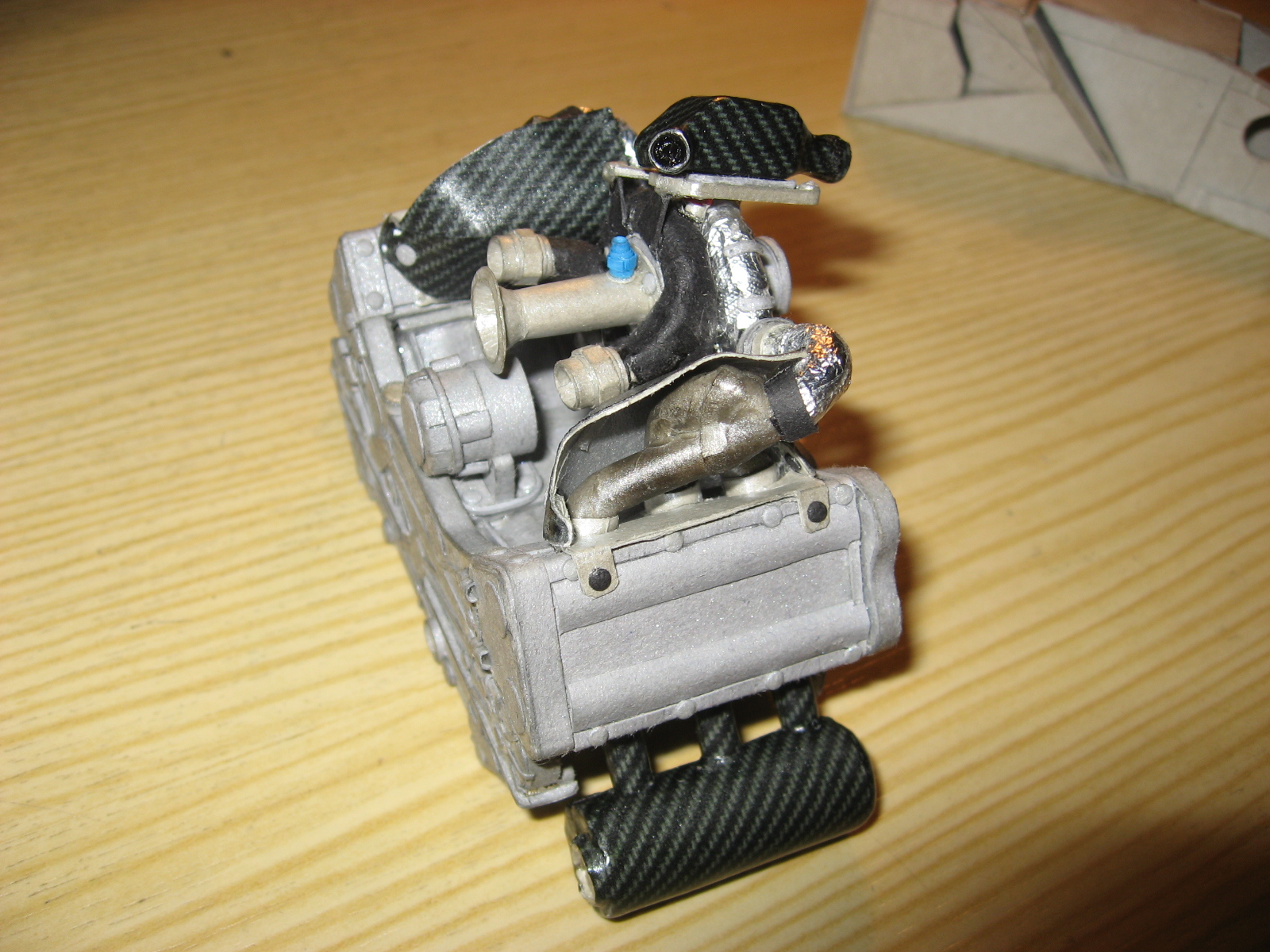
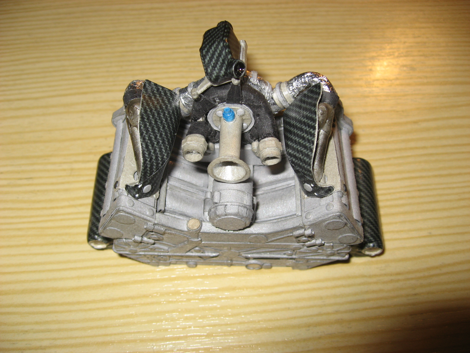
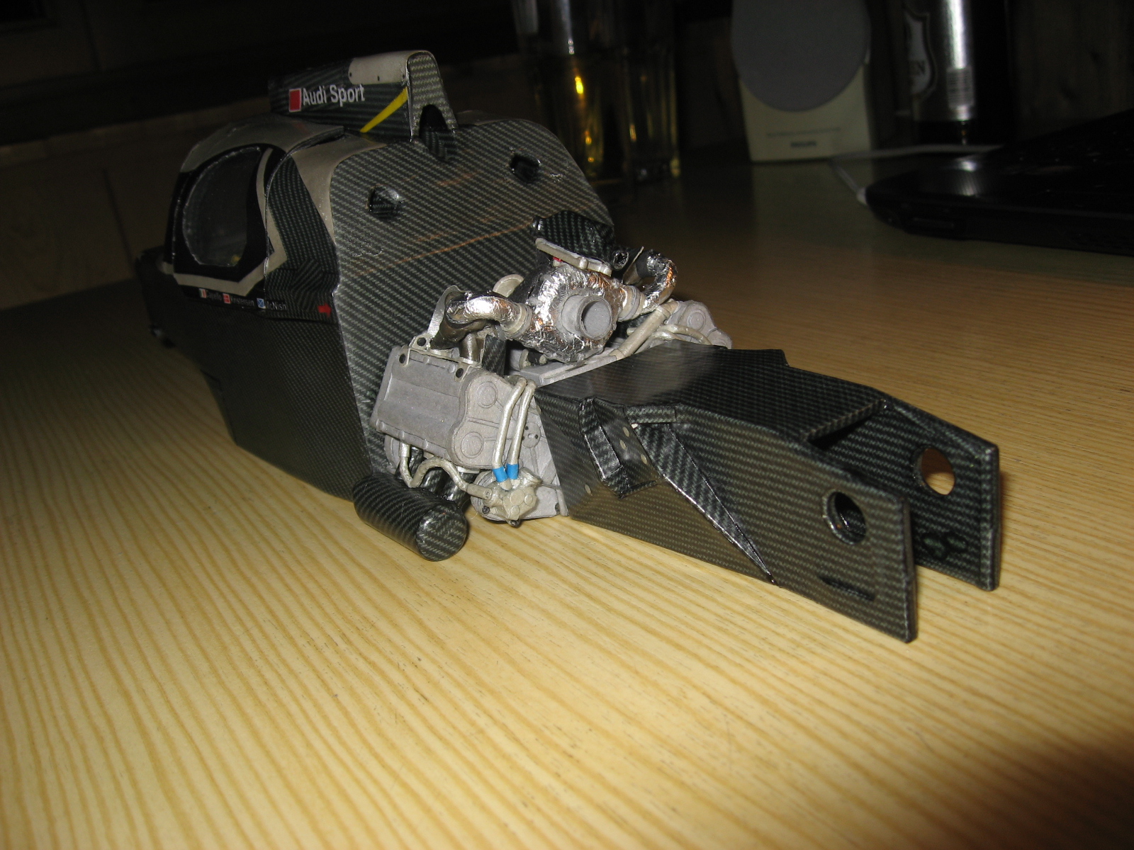
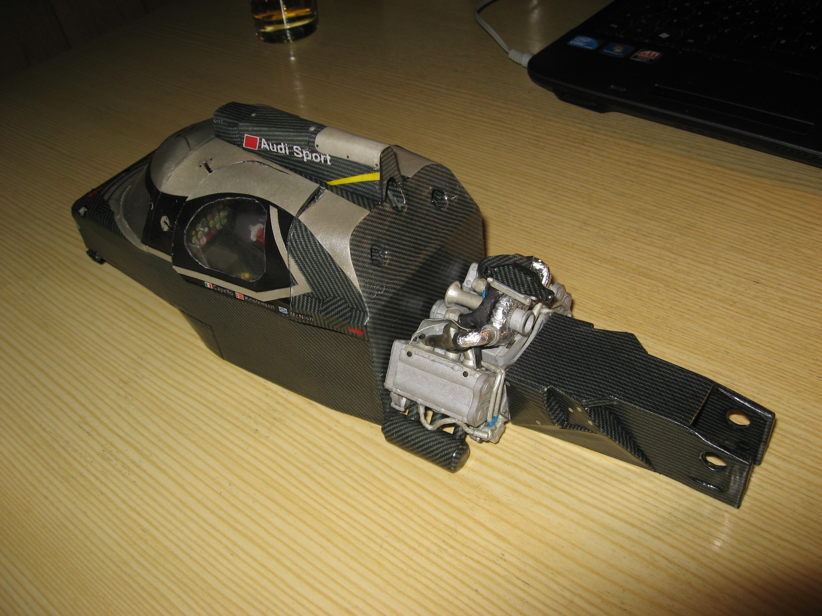
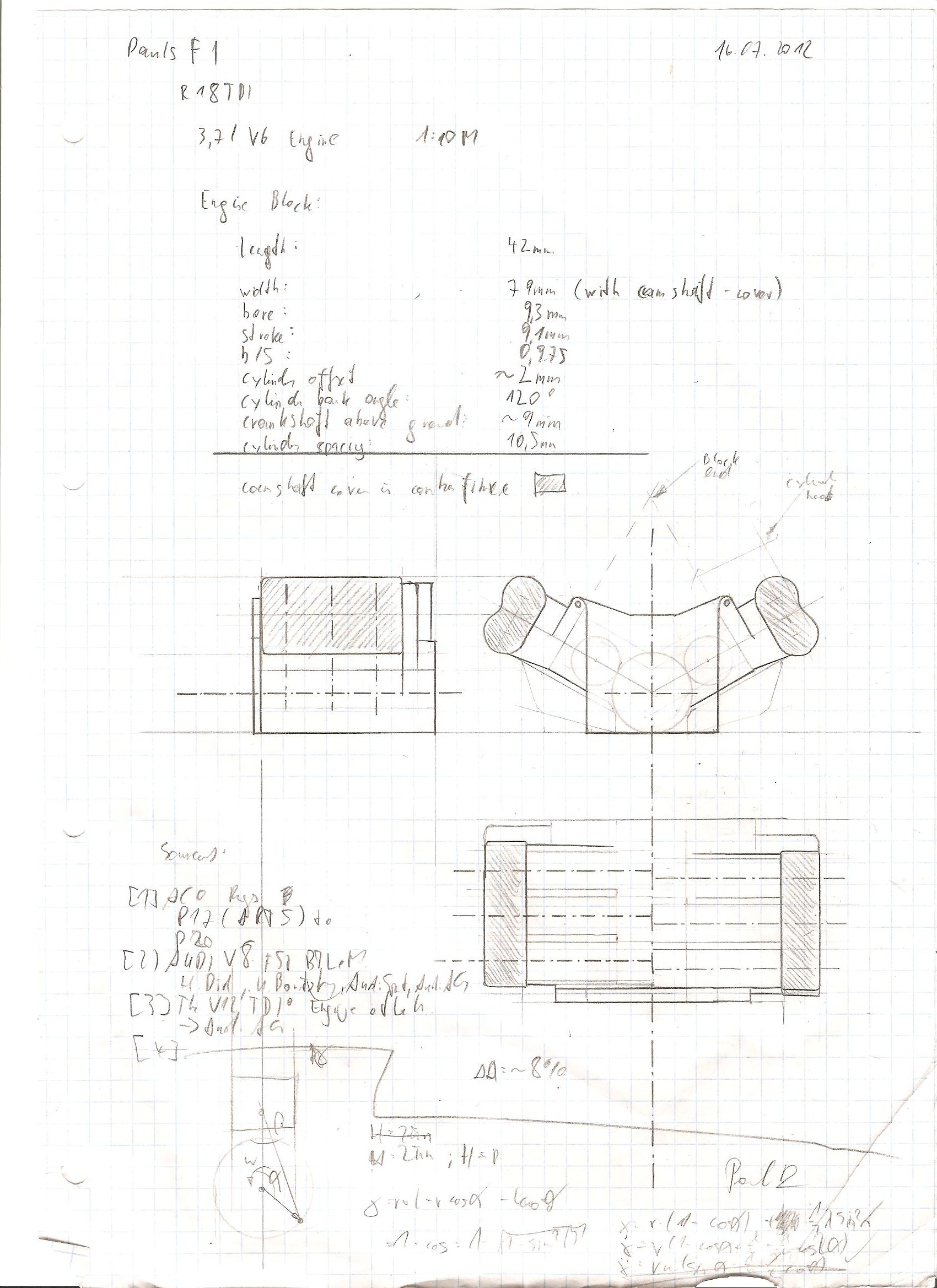
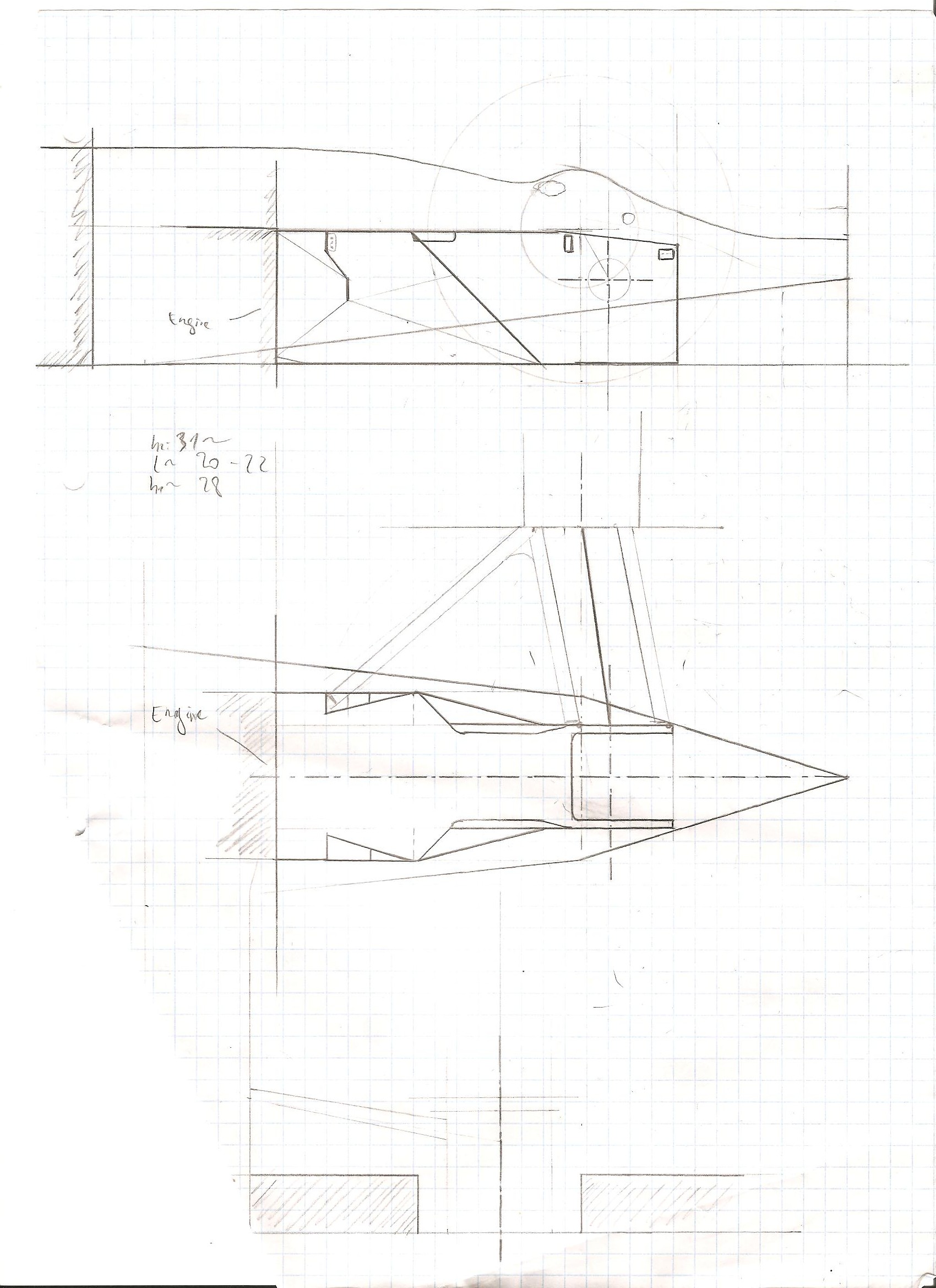
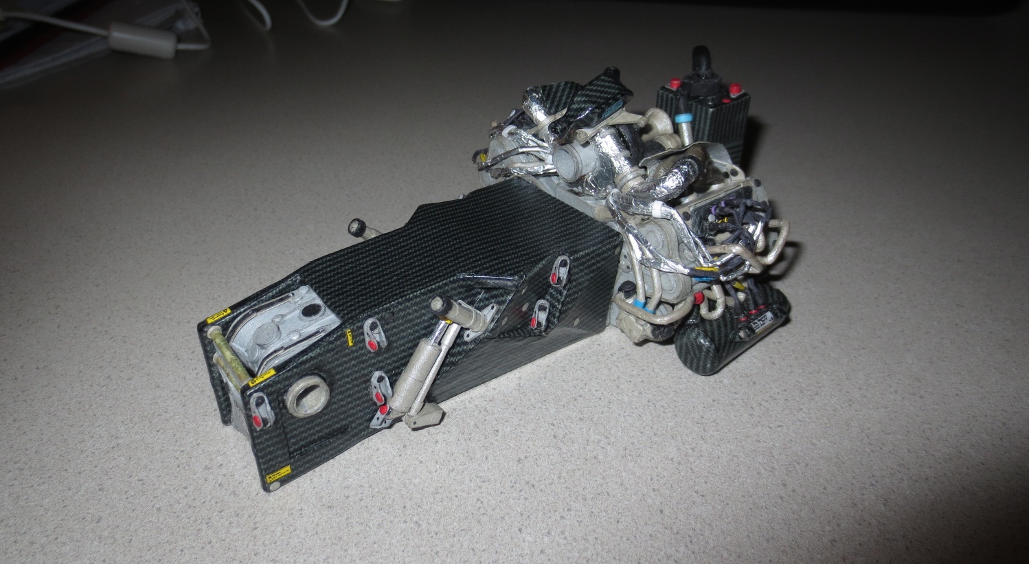
As you can see on the pictures, there's a lot of progress at the engine and the gearbox.
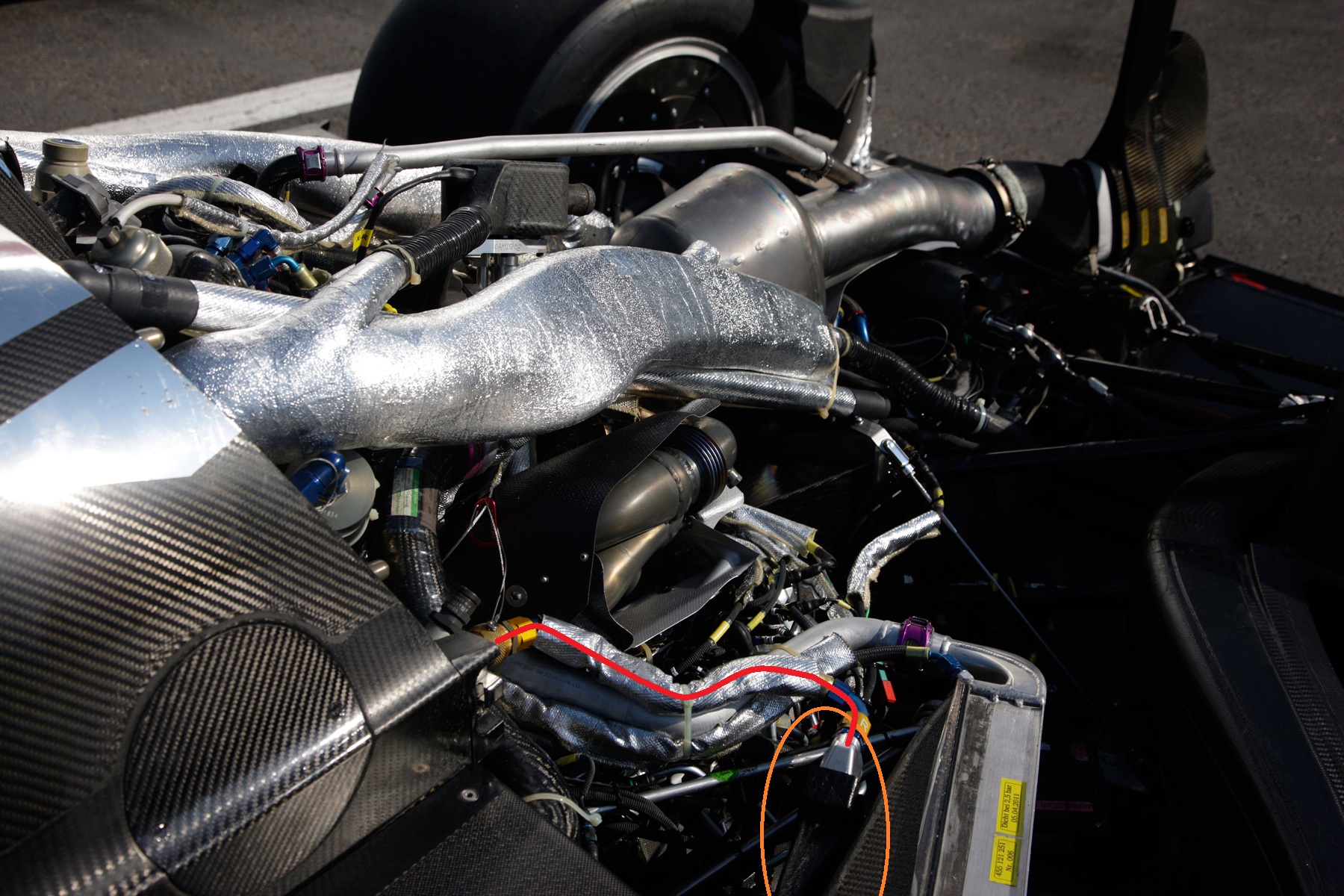
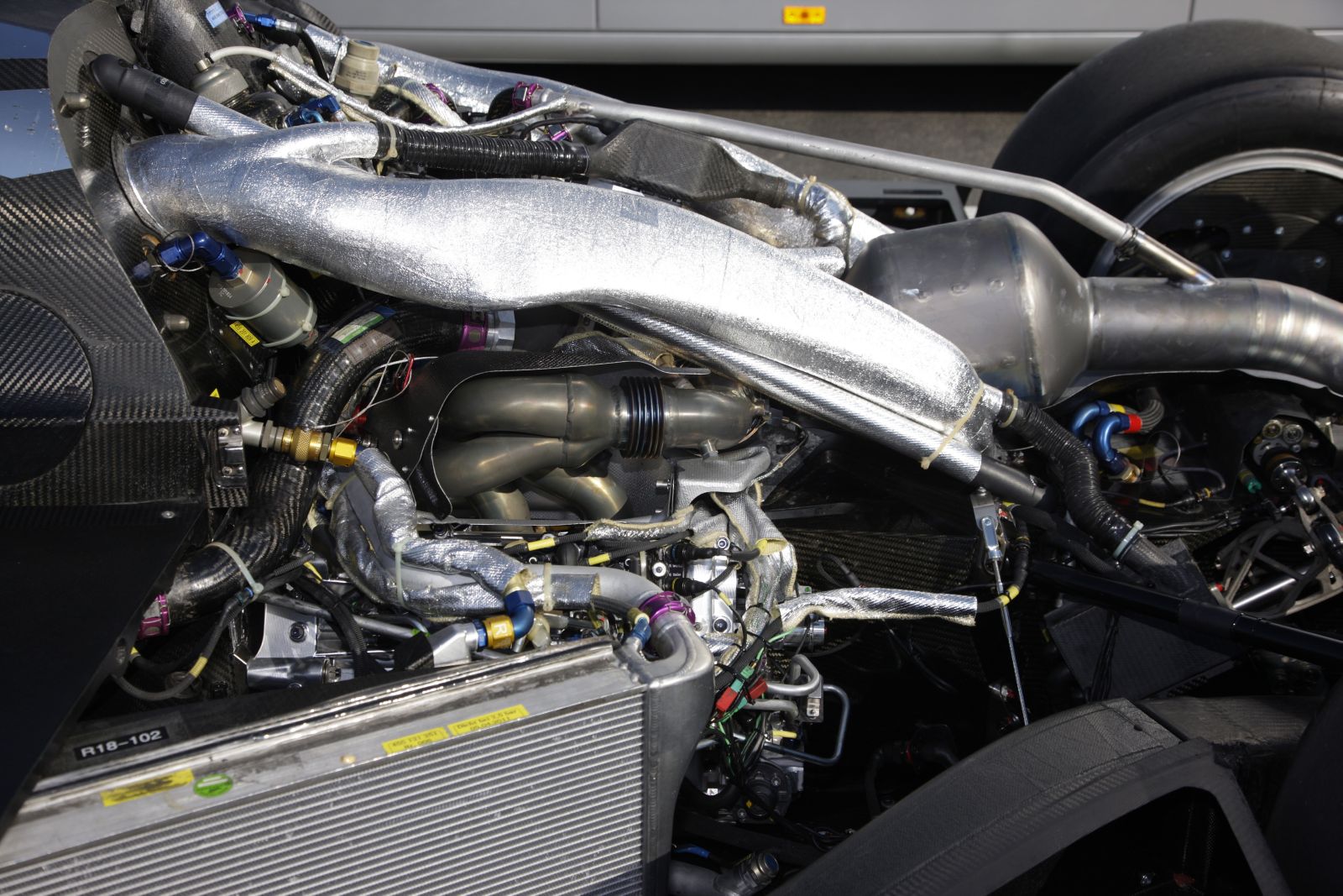
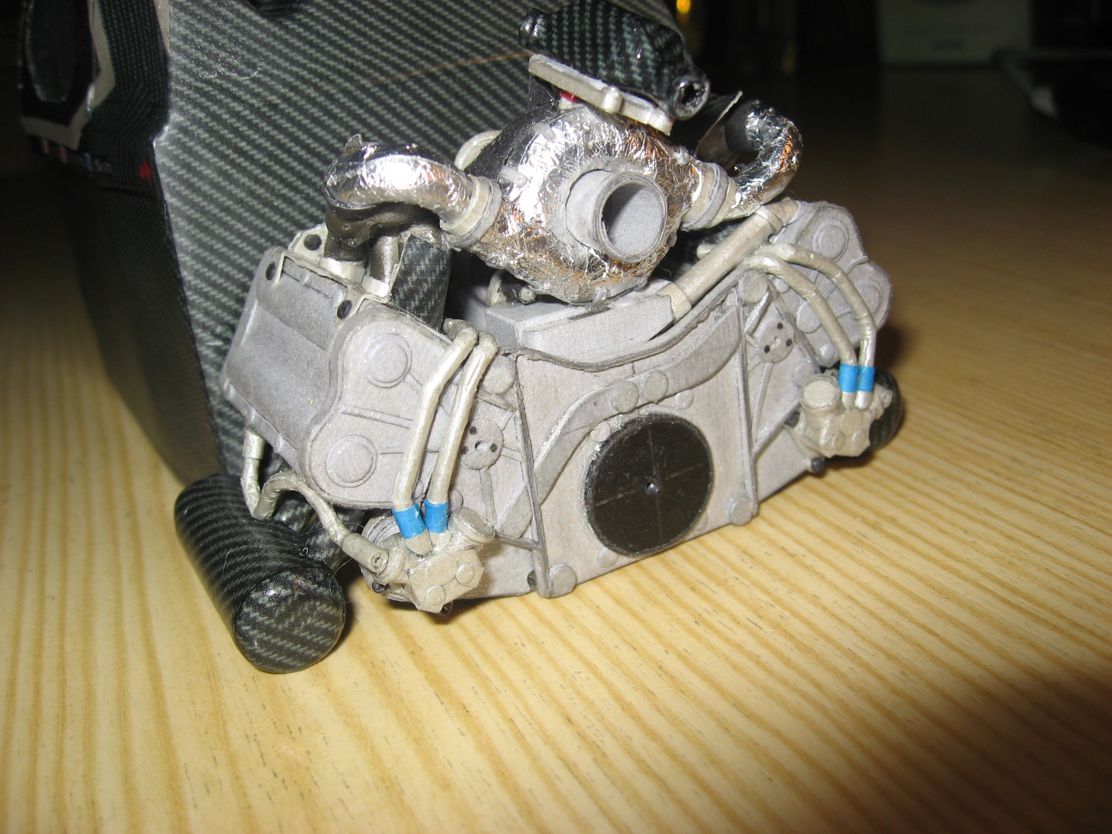
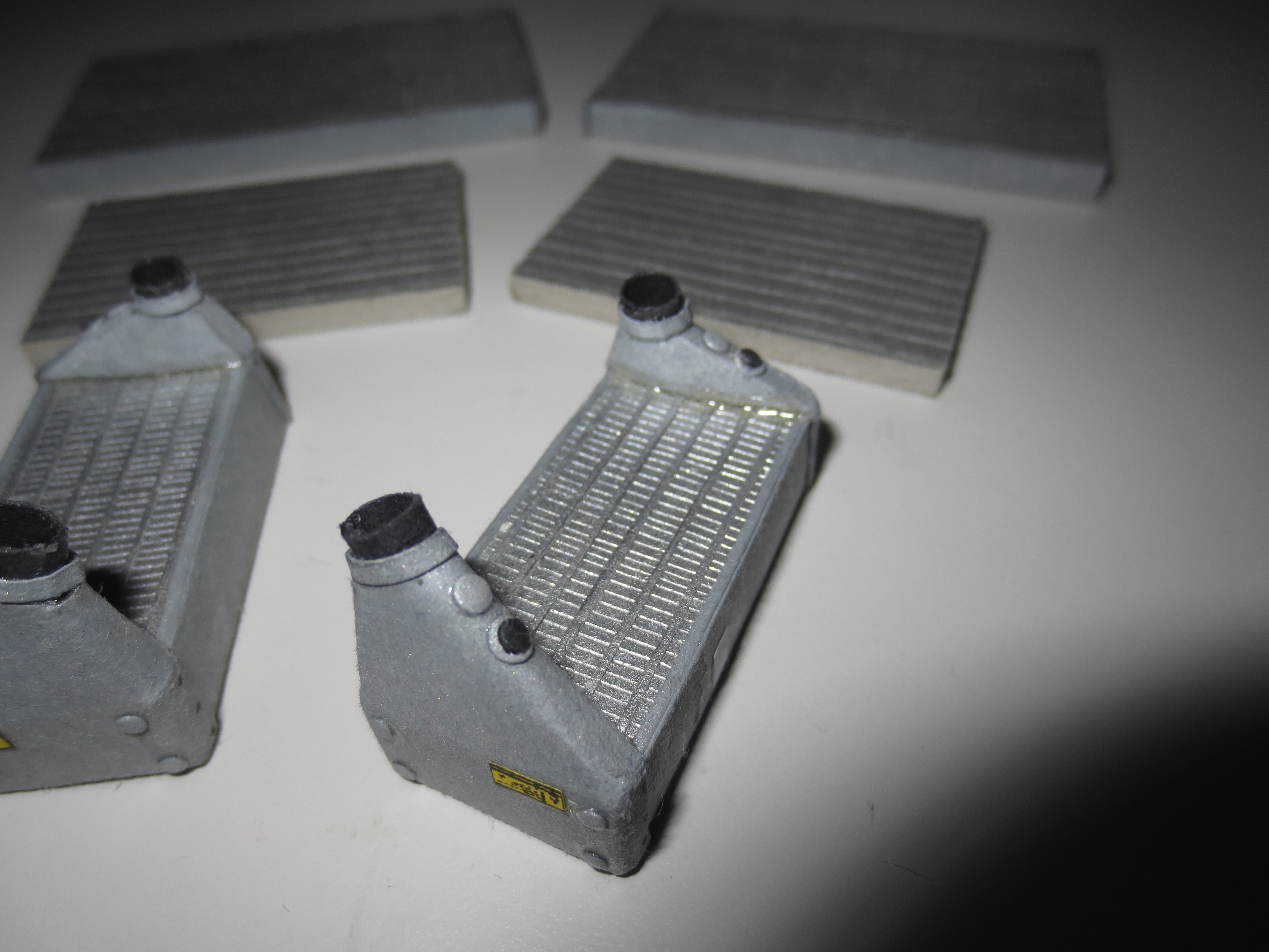
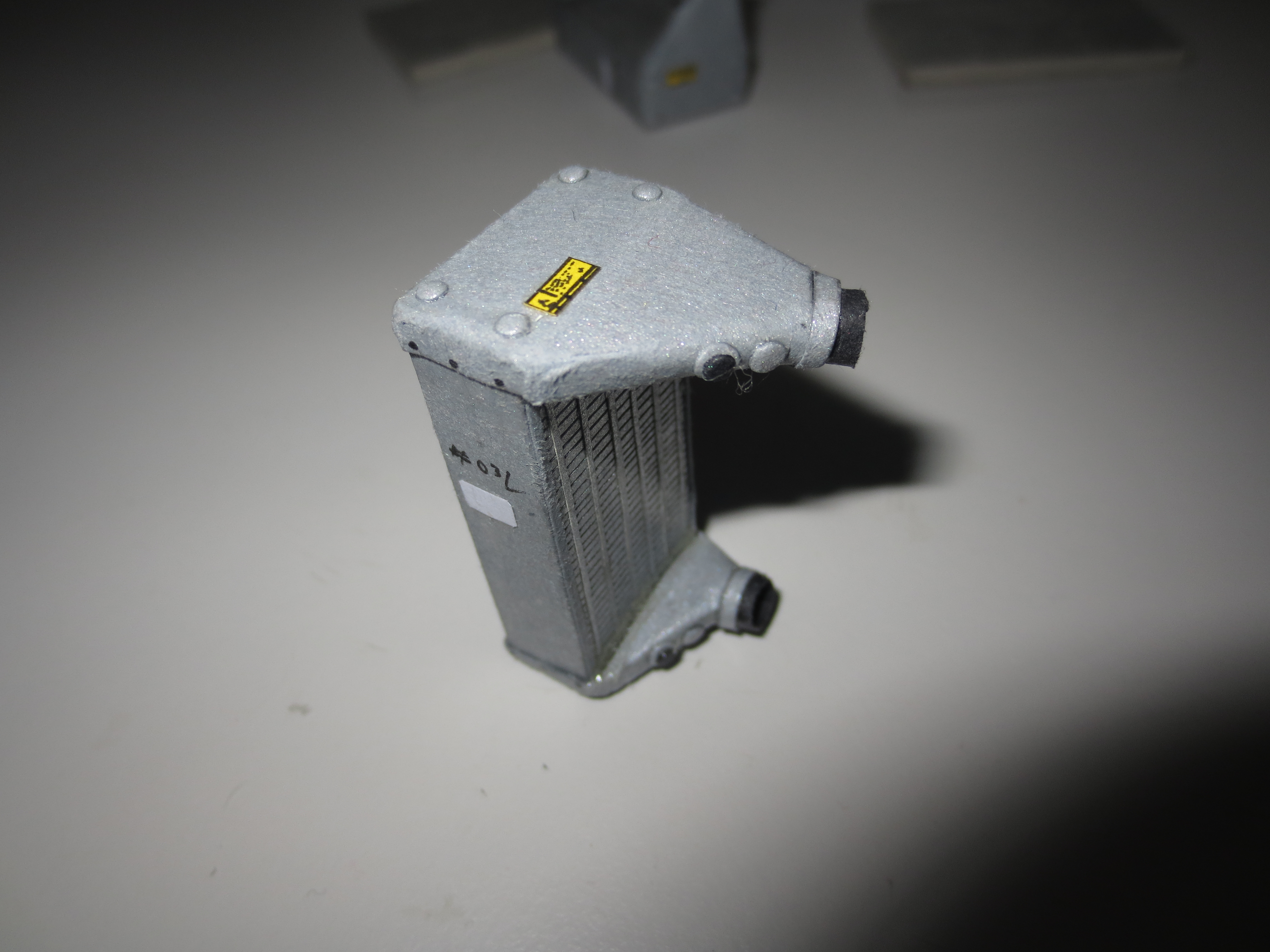
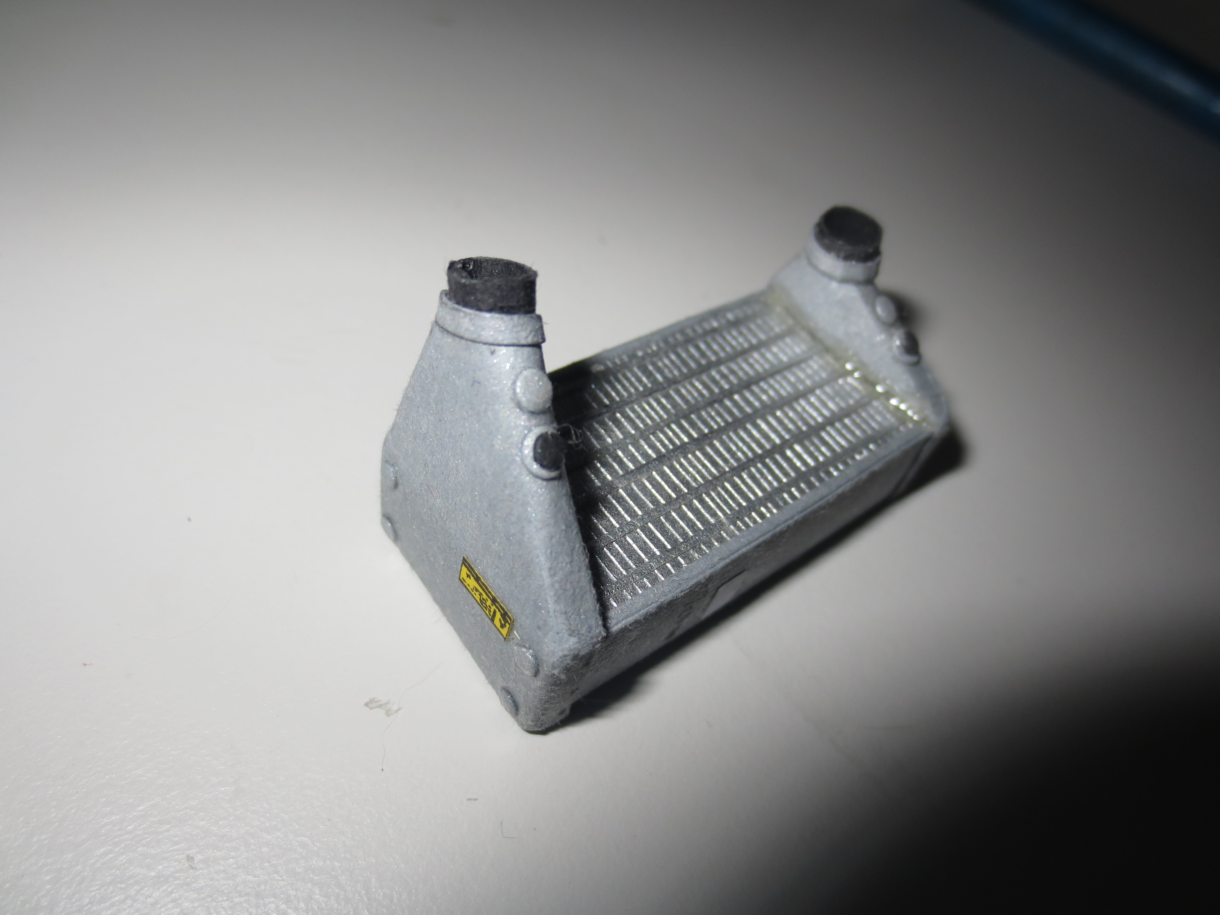
I did most of the electrical wiring of the engine. I have to say, that I do not understand the electrical injection valve control system completely. But I interpreted it in a way, that it could work. Next thing to do on the engine is the whole cooling system. Namely water-and fuel cooling and the intercoolers. The big silver pipes, that come out of the monocoque, which transports the "used" air from the cockpit are for cooling some items at the engine and the gearbox. One item is for example the VTG (Variable Turbine Geometry) control unit. That's the carbon fibre box on top of the turbo charger. There are also some items at the gearbox, but I do not know their role yet. But one of them should be the gearbox oil radiator I guess.
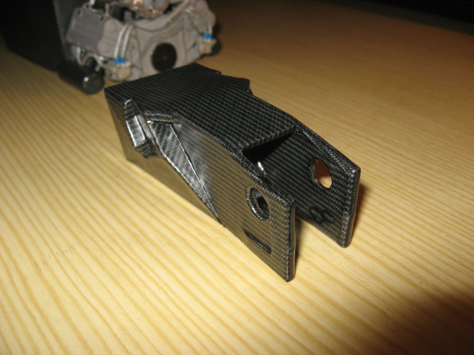
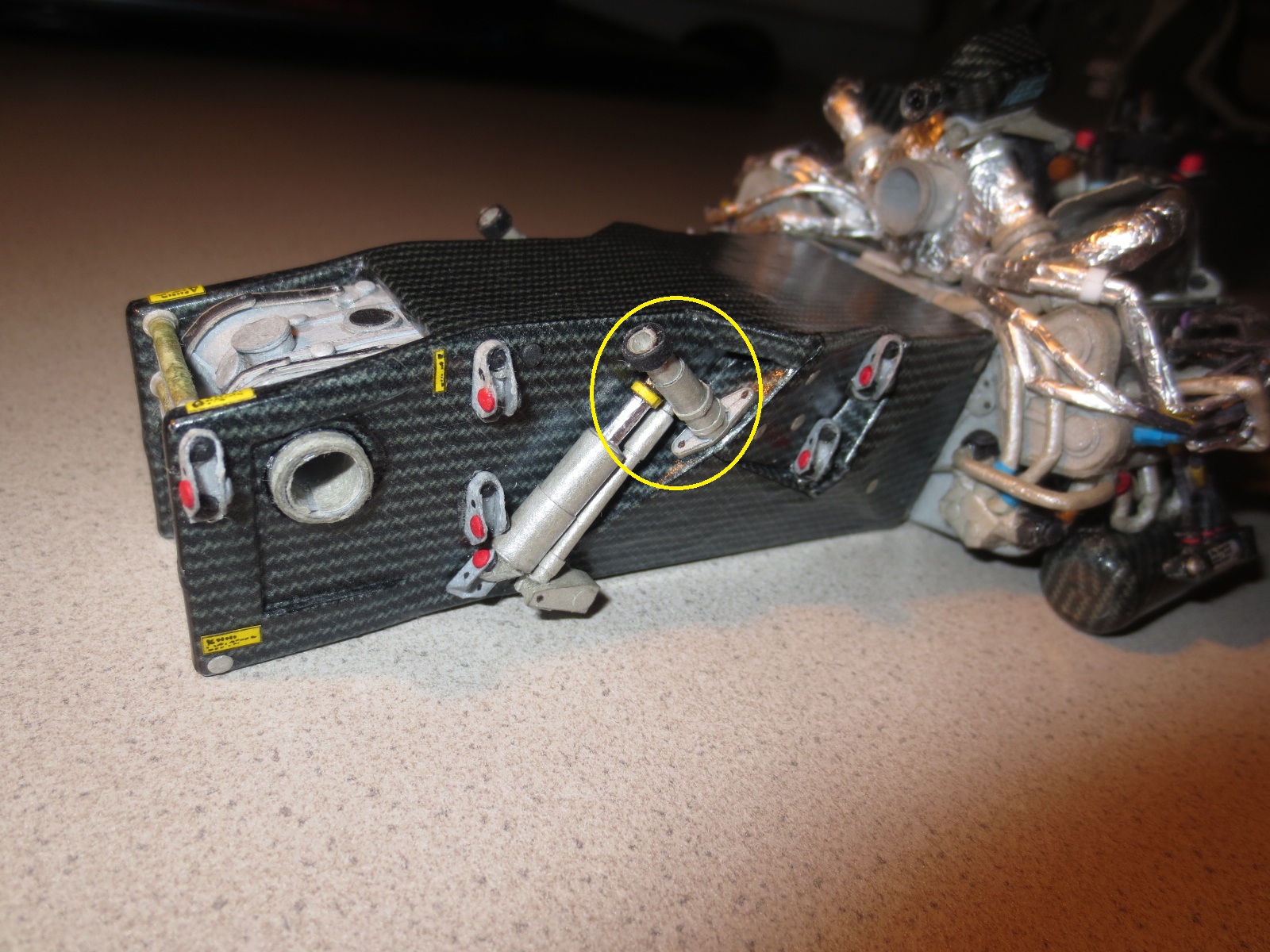
I also finished the whole gearbox casing. The casing itself is quite empty, only the drive shaft and the differential housing is in there. At the gearbox housing itself, I mounted a few suspension items. As for example, brackets, dampers, torsion bars and the anti roll bar.
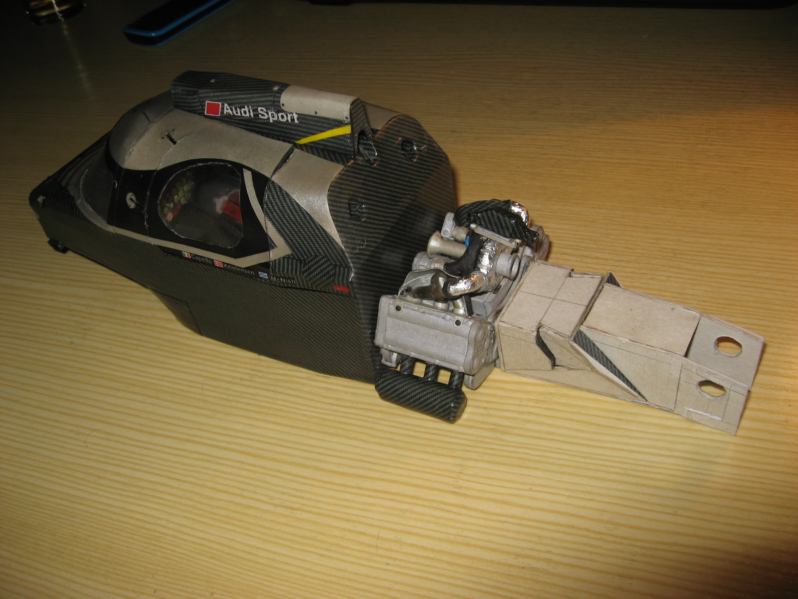
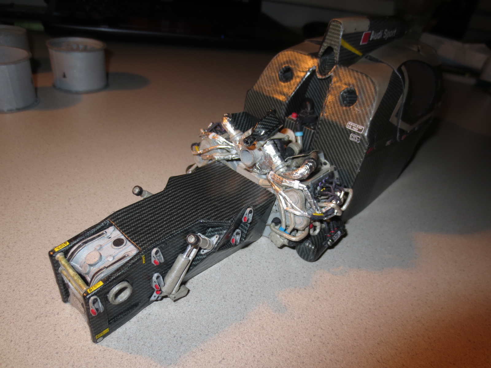
That's the engine-gearbox unit. It's not completely finished yet, but not very much is missing.
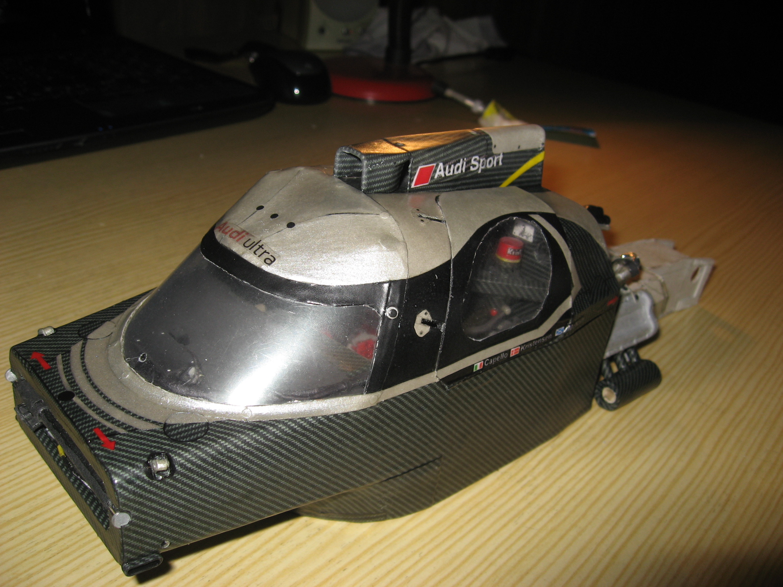
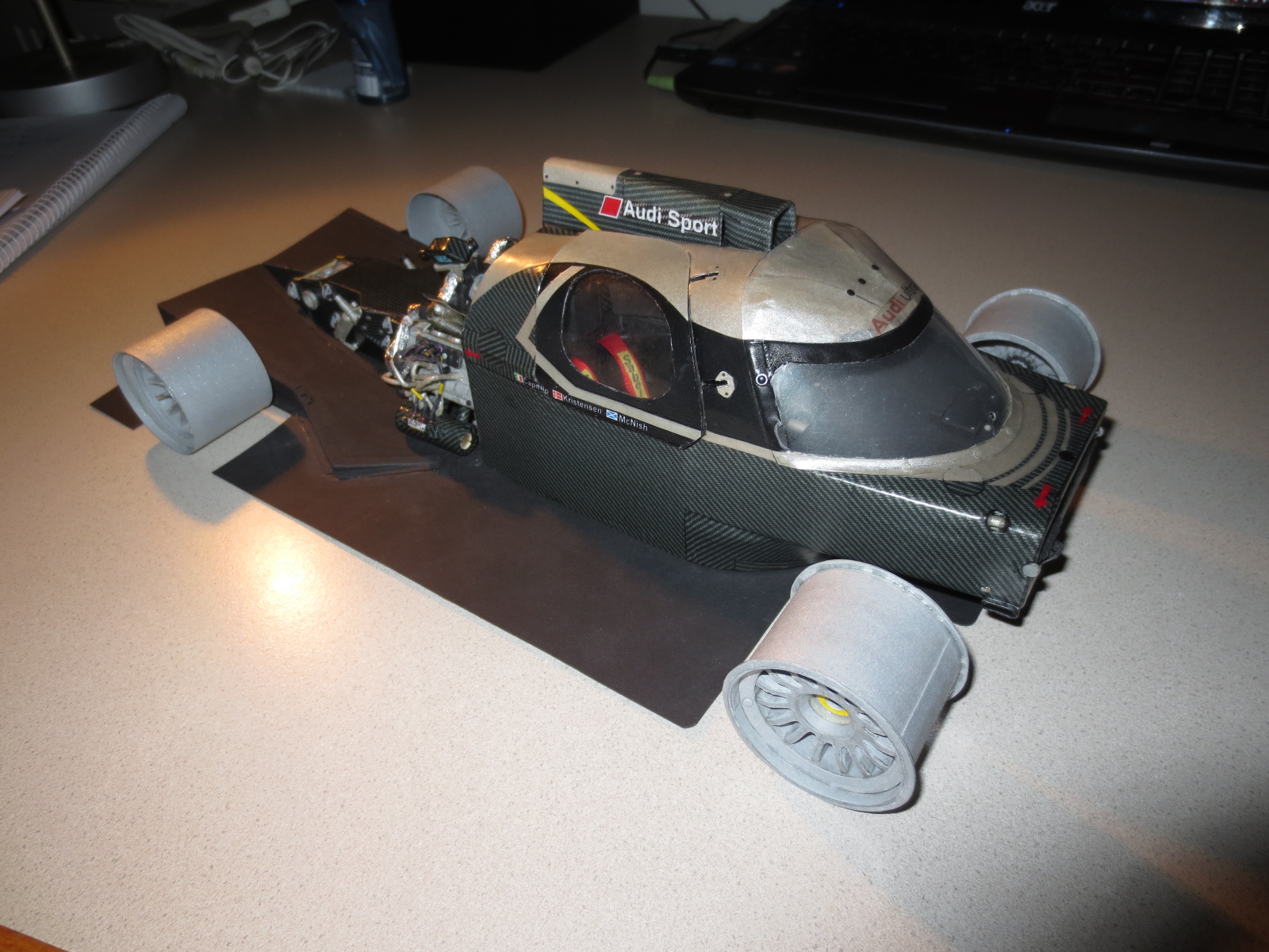
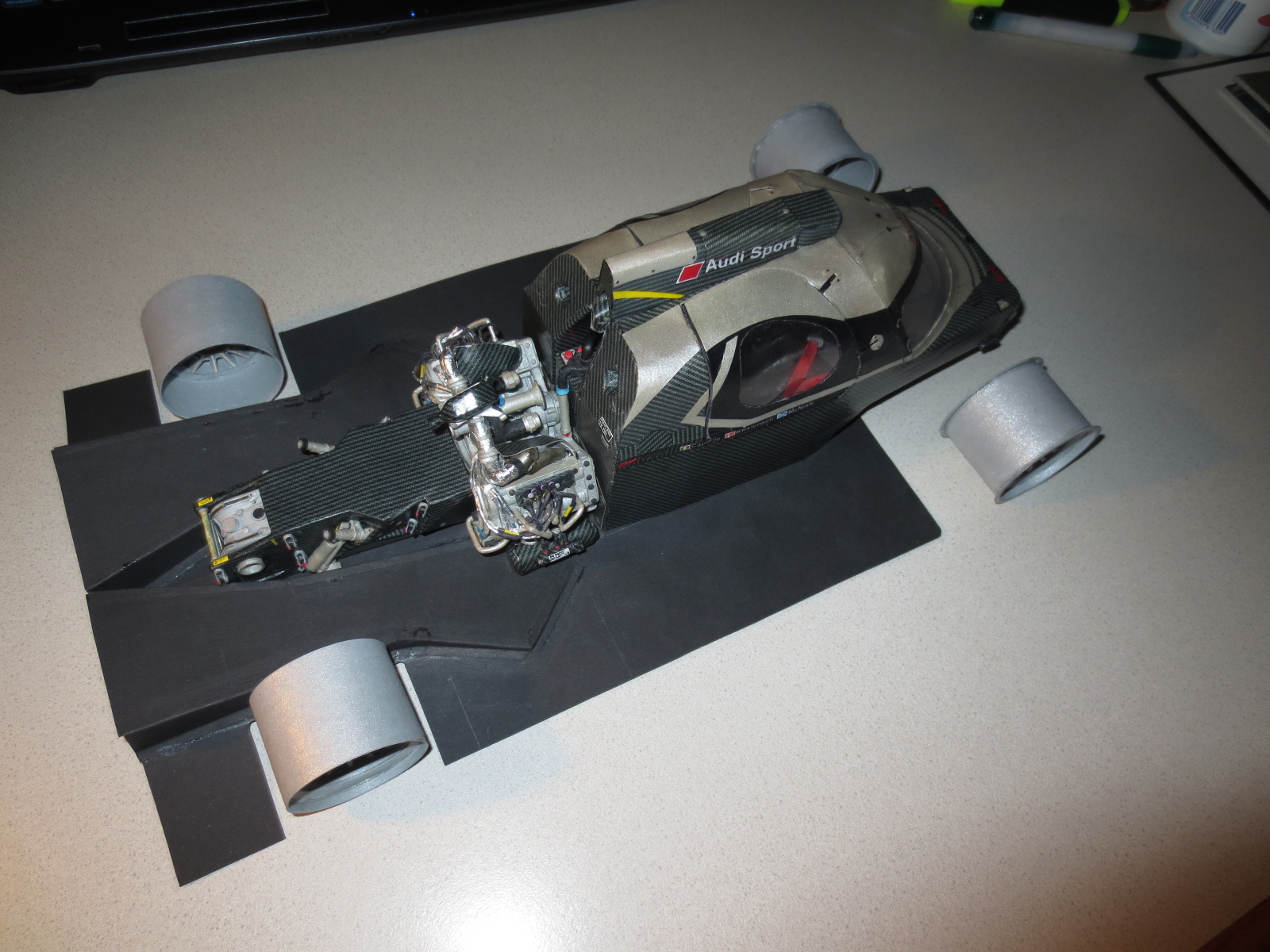
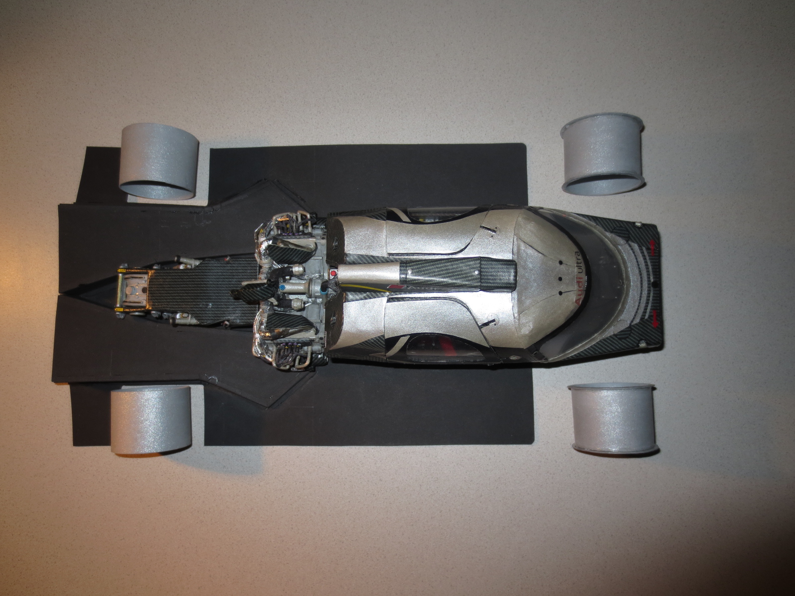
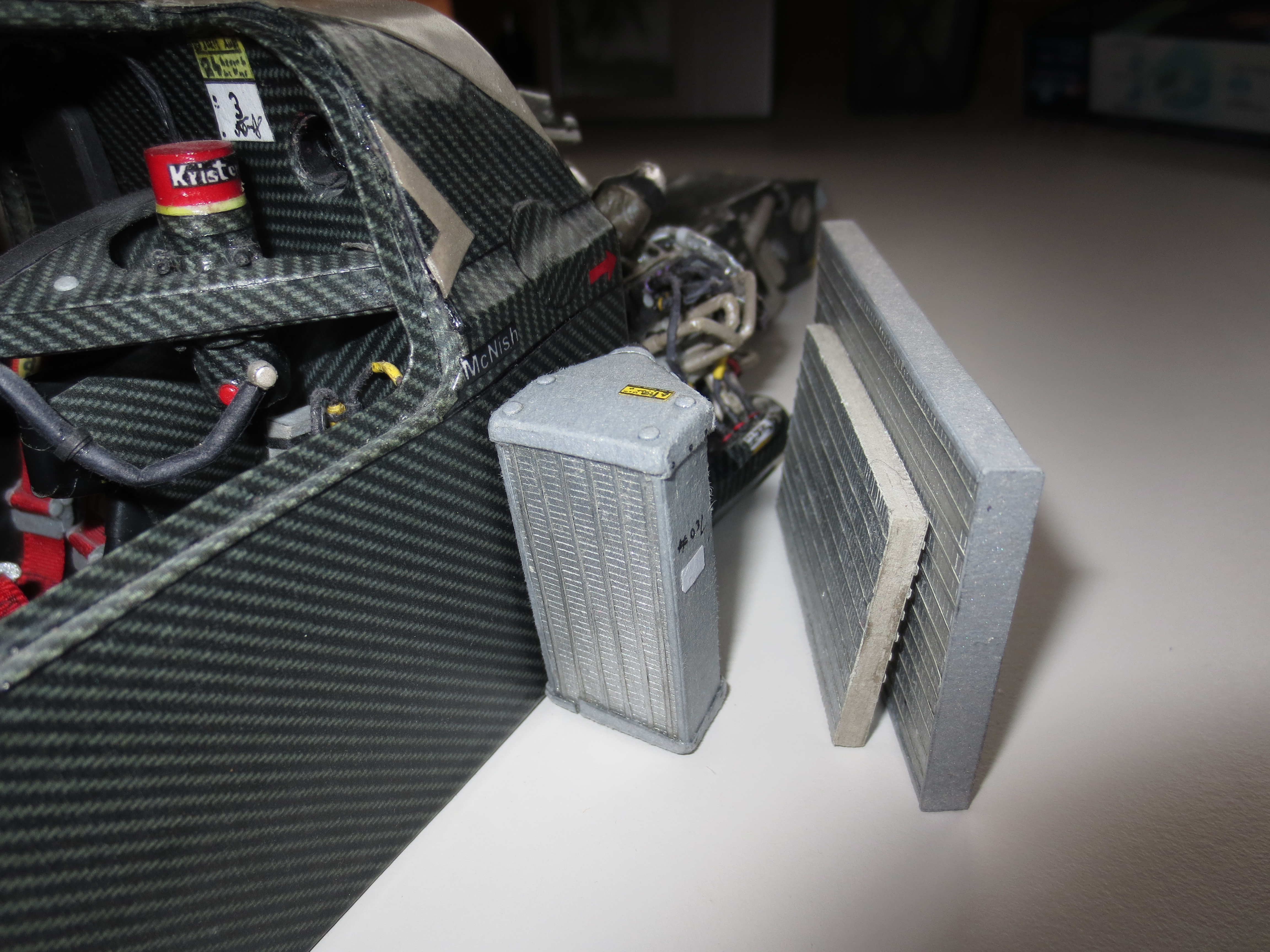
The unit, placed at the monocoque. After fitting it, I can start with the whole cooling arrangement, which is enormously large in comparison to a F1 cooling system.
Here you can see the cutout. It's a quite clean work, as I wrote, satisfying, but not perfect.
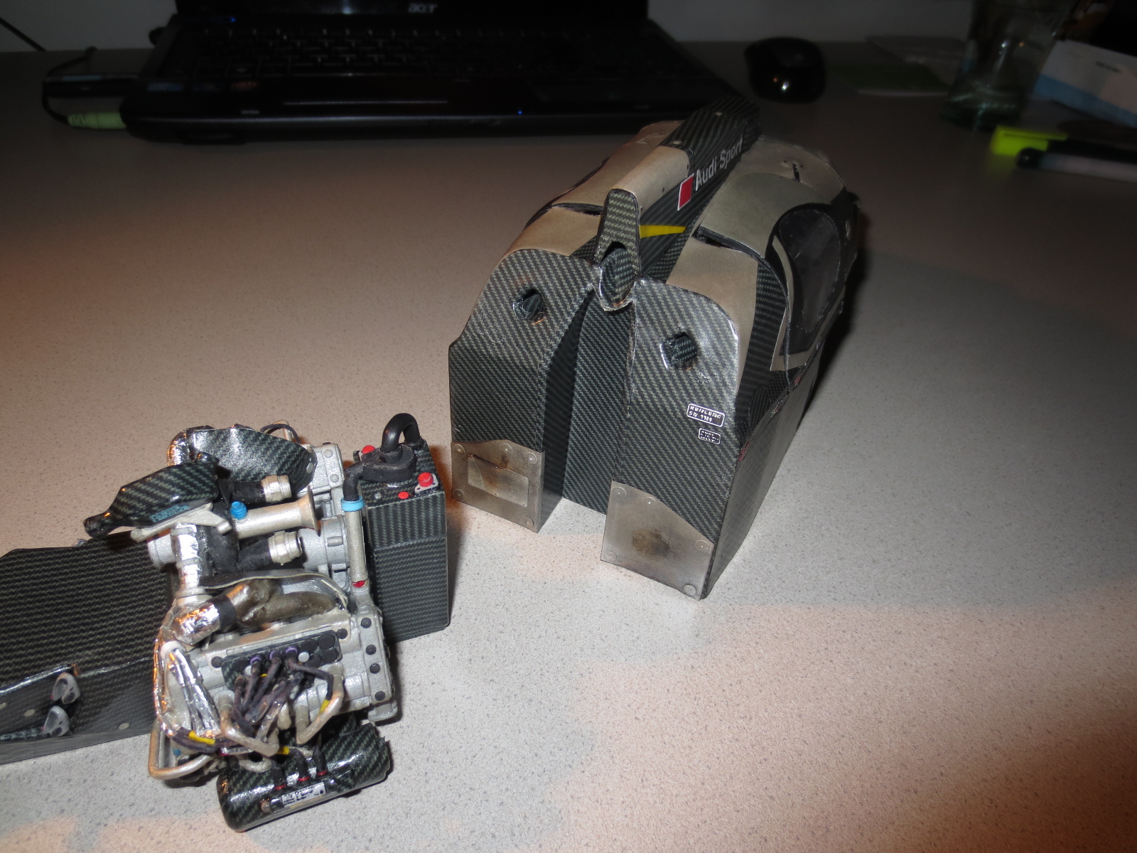
A good view on the oil tank. The lower part is the main tank, the upper part is the collecting system. LMP1 cars must have two collector tanks. A catch tank with minimum 3 litres and an extra tank with another litre.
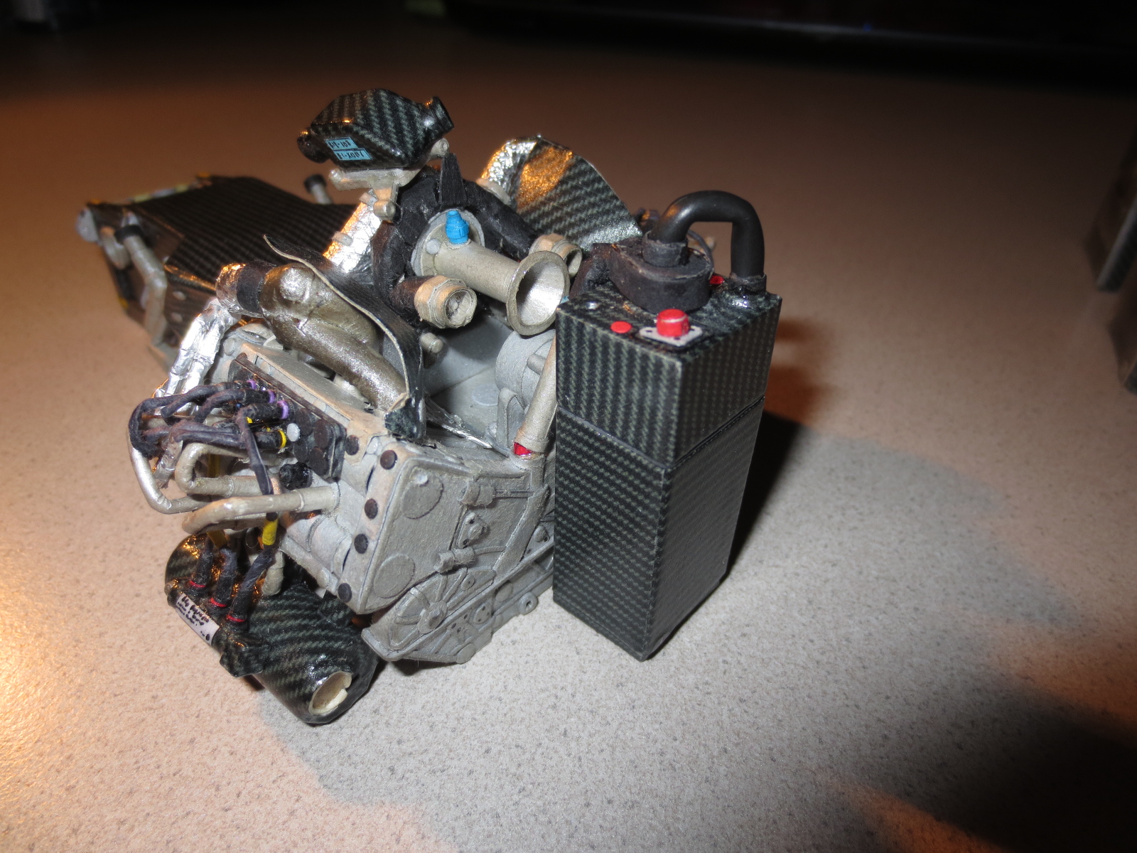
A view on the injection valve control system (not completely finished yet).
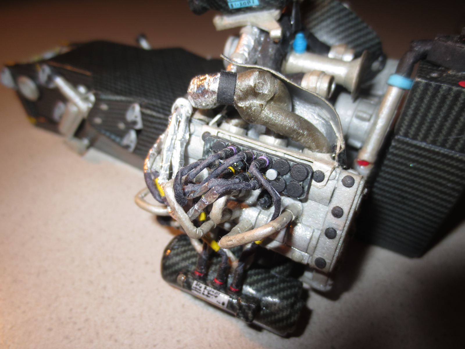
Another view of the engine.
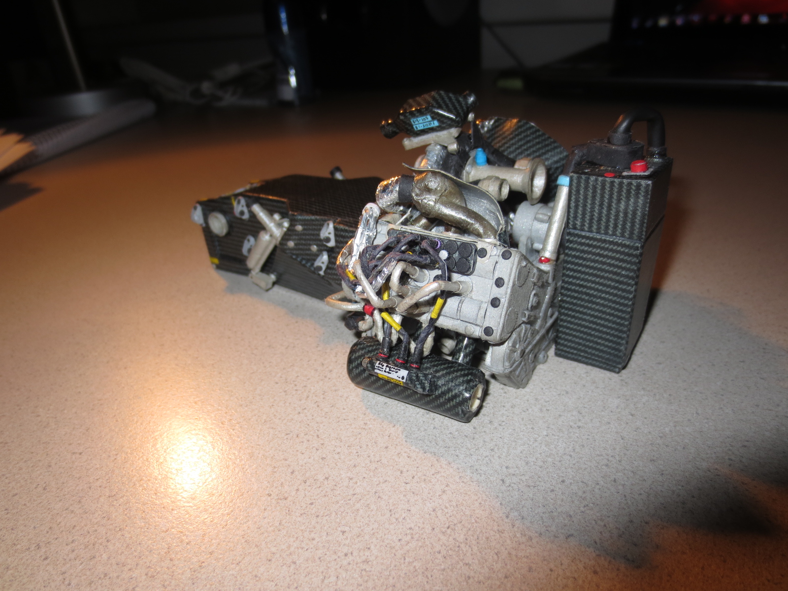
Here you can see the differential casing. At the 2012 model this is also out of carbon fibre.
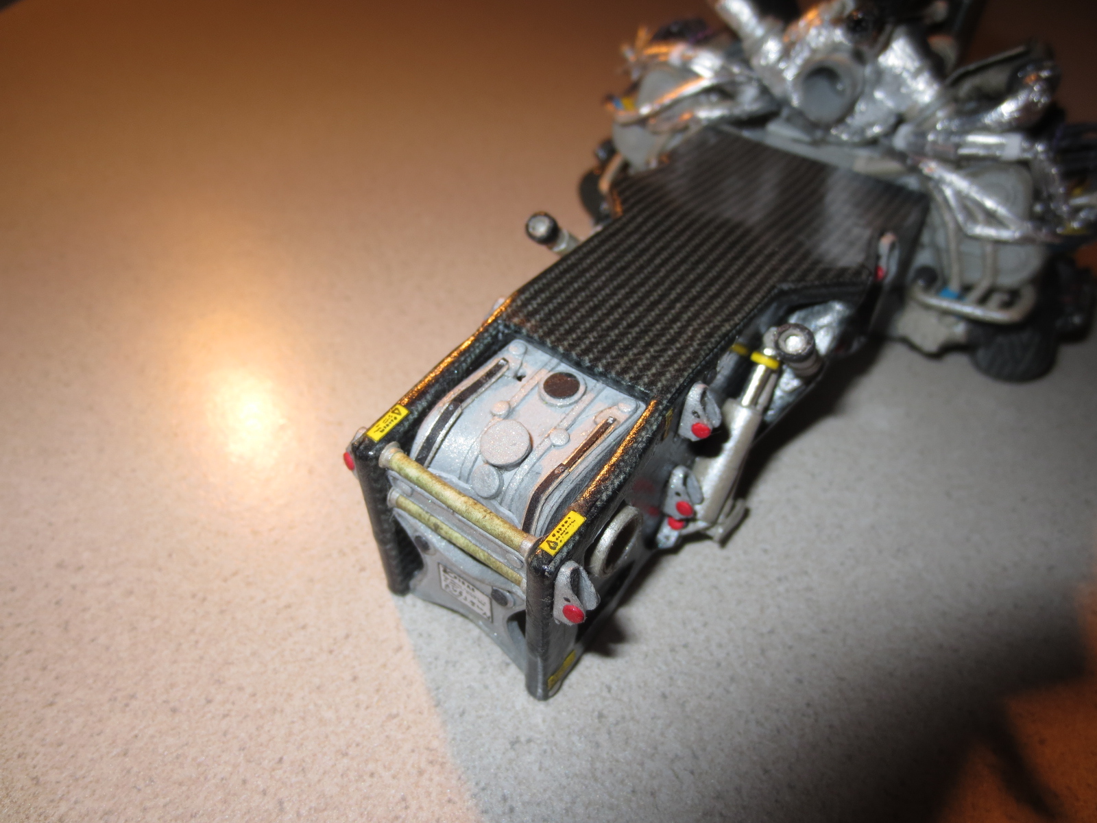
The gearbox housing. As you can see, I again looked exactly on the direction of the carbon fibre sheets. You can clearly see the five brackets for the two wishbones and the track rod at the very rear. Also you can see the anti roll bar under the damper and the torsion bar spring (yellow circle). The third damper and the rocker arms for the push rods are missing.
That's it for the mo,
Cheers
Paul
