2 stroke thread (with occasional F1 relevance!)

All that has to do with the power train, gearbox, clutch, fuels and lubricants, etc. Generally the mechanical side of Formula One.
tok-tokkie
tok-tokkie
37
Joined: 08 Jun 2009, 16:21
Location: Cape Town

Re: 2 stroke thread (with occasional F1 relevance!)

Post

Thanks for the extended answer to my query about in line engines. I had envisioned that the heads were at 90° to how you have them. I thought the two exhaust ports faced outwards & the spark plug and inlet port were along the centerline between the cylinders. Your layout eliminates the problems I had envisioned.

Your latest post makes me now realise that there really is no gas pressure forcing the rotary valve against the outer exhaust port. As shown by your spanner (wrench) analogy the gas pressure is carried by the metal rotary valve body so the two sides balance each other. In your post in reply to my query you stated that the whole rotary valve can move axially so as to align itself between the two ports. Your valve neatly sidesteps the big gas sealing, friction and lubrication problem that most other rotary valve designs have. A very elegant concept indeed.

manolis
manolis
107
Joined: 18 Mar 2014, 10:00

Re: 2 stroke thread (with occasional F1 relevance!)

Post

Hello Brian Coat.

Let’s see the opening and closing of the valves of the Desmodromic cylinder head of the Ducati Panigale 1299 from the energy viewpoint (the previous analysis was based on a rough approximation of the force necessary for the motion) .

The valve lift is 16mm, the total “reciprocating” mass is taken 100gr.

The engine makes its peak power at 10,500rpm.

10,500rpm of the crankshaft means 1.5*10,500=15,750rpm for the valve reciprocation (in 240 crankshaft degrees the valve makes a full reciprocation) .

For simplicity the valve lift profile is taken as pure sinusoidal (any difference from the pure sinusoidal increases the required forces and the friction).

Initially the opening cam lobe has the control over the intake valve.

During opening, at the middle of its stroke the valve has a linear speed of 13m/sec (pi*0.016m*15,750/60). Its kinetic energy is 1/2 * 0.1Kg * (13 m/sec)^2 = 8.5J

This energy is provided to the valve by the opening camlobe through the opening rocker arm.

After the middle stroke the control of the valve passes to the closing camlobe.

When fully opened, the valve has zero kinetic energy. From the middle stroke to the full open position, the closing camlobe, through the closing rocker arm, absorbs the 8.5J of the valve (the valve has zero speed and so zero kinetic energy).

During closing, at the middle of its stroke the valve has again 8.5J kinetic energy; this energy came from the closing camlobe by means of the closing rocker arm.

After the middle of its stroke the control of the valve passes to the opening cam lobe, again. The opening camlobe decelerates the valve and absorbs the 8.5J of its kinetic energy.

In a second the valve opens and closes 0.5*(10,500/60)=87.5 times (the camshaft rotates with half crankshaft speed).

According the previous, during a second, 8.5+8.5=17J have passed between the valve and the camshaft 87.5 times. This is 1,5kW (2PS) for one valve.

There are 8 valves in total (the heavier exhaust valves have shorter stroke, so the kinetic energy is more or less the same with the kinetic energy calculated for the intake valves), which means 12kW (16PS).

The previous were calculated with 100% efficiency of the kinematic mechanism (in the meaning that in order the valve to absorb 8.5J kinetic energy, the camshaft provides only 8.5J energy).

If the Desmodromic valve train of the Panigalle 1299 operates with 50% energy recovery (quite doubtful) the power required for the valve train at 10,500rpm is 6kW (8PS).

If the Desmodromic valve train of the Panigale 1299 runs with 25% energy recovery, it requires 9kW (12PS) at 10,500rpm

Most of the friction is at the contact point between the rocker arms and the camlobes, and there is no way to have hydrodynamic lubrication there:


Image

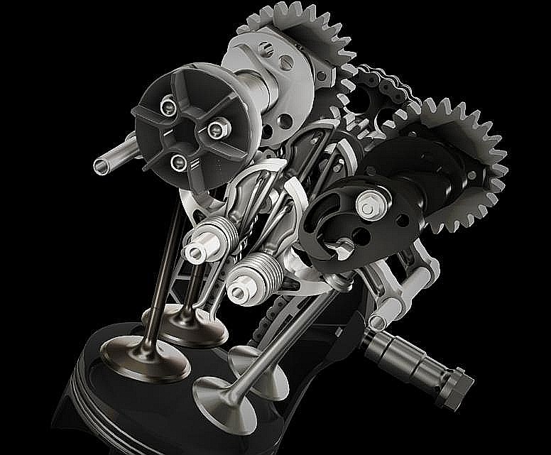
Spot on the big diameter "closing" camlobe and its rocker arm. Looking at it, I seriously doubt about its capacity to recover more than, say, 25% of the energy.


Now see the previous post with the extreme-over-square Ducati Panigalle with the 128mm bore, the 50mm stroke, the 10% bigger valves (17.7mm valve lift) and the 14,000rpm rev limit.

At 14,000rpm, 17.7mm valve lift and 20% heavier valves (0.12Kg instead of 0.1Kg, which is a small increase considering the 10% increase of the valve diameter), the maximum speed of the valve becomes 20m/sec,
which means a kinetic energy equal to 0.5*0.12Kg*(20m/sec)^2=24J.
24J+24J=48J and 0.5*(14,000/60)=116.7,
so the power required is: 48J * 116.7/sec = 5.6kW per valve,
which makes 45kW (60PS) for the eight valves of the two cylinder heads of the modified Panigale 1299.

This power has to reciprocate between the camshafts and the valves.

Depending on the energy recovery, the net power necessary for the valve train is calculated.
For instance, with 25% energy recovery, the valve train consumes 33kW (45PS), with 50% energy recovery the valve train consumes 22kW (30PS).

Even with 75% energy recovery the energy consumed by the valve train of the modified Panigale at 14,000rpm is 11kW (15PS).

Worth to mention: the timing chain has to be capable to pass the complete 60PS of power, no matter how much is recovered.


Do I miss something?
Is it out by one order of magnitude?

Thanks
Manolis Pattakos
Last edited by manolis on 03 Aug 2016, 06:22, edited 1 time in total.

manolis
manolis
107
Joined: 18 Mar 2014, 10:00

Re: 2 stroke thread (with occasional F1 relevance!)

Post

Hello Tok-tokkie.

You write:
"Your latest post makes me now realise that there really is no gas pressure forcing the rotary valve against the outer exhaust port. As shown by your spanner (wrench) analogy the gas pressure is carried by the metal rotary valve body so the two sides balance each other. In your post in reply to my query you stated that the whole rotary valve can move axially so as to align itself between the two ports. Your valve neatly sidesteps the big gas sealing, friction and lubrication problem that most other rotary valve designs have. A very elegant concept indeed."


While there are many animations and lots of explanations and drawings in the http://www.pattakon.com/pattakonPatRoVa.htm web page, it seems only few people did achieve, so far, to understand the way the PatRoVa rotary valve operates.

And you are one of them.

Can you, please, help me to understand what is so confusing about the PatRoVa rotary valve?

Thank you
Manolis Pattakos

Brian Coat
Brian Coat
99
Joined: 16 Jun 2012, 18:42

Re: 2 stroke thread (with occasional F1 relevance!)

Post

Manolis: Your assumptions are wrong.

There is loads of published information which shows that cam/follower FMEP at high speed in high performance engines in the *tenths* of Bar range.

There is plenty of published data showing how cam/follower tribology works, including when it is/isn't boundary/mixed/hydrodynamic.

You are approaching the subject from first principles and applying (some) guessed assumptions to reach conclusions which are (i) contradicted by real-world data (ii) contradicted by the known understanding of how poppet valvetrains work and why.

This does not mean the PatRova is not a good idea but I wouldn't hang my had on big power gains from reduced valve train losses if I were you. :D

tok-tokkie
tok-tokkie
37
Joined: 08 Jun 2009, 16:21
Location: Cape Town

Re: 2 stroke thread (with occasional F1 relevance!)

Post

Manolis,
Your GIF animations are very clear but they run so fast I have difficulty understanding and 'seeing' what is taking place. In particular the V6 gif I would have liked to pause it and step through the the file. Can you make a YouTube vid of them so we can do that?
The stereopscopic ones I have tried to see in 3D but failed.
But I really like your system.

manolis
manolis
107
Joined: 18 Mar 2014, 10:00

Re: 2 stroke thread (with occasional F1 relevance!)

Post

Hello Brian Coat.

You write:
“Manolis: Your assumptions are wrong.”


The only assumption I’ve made is the percentage of the energy recovery.

All the rest calculations are simple physics and maths.

The calculations say that at extreme revs (wherein only few engines can operate) the reciprocation of energy between the crankshaft and the valve train is a significant percentage of the energy provided by the engine.

The calculated 45kW (60PS) at 14,000rpm to and fro the cylinder heads of the modified Panigale has nothing to do with assumptions.
The valve performs a specific motion.
The instant speed of the valve varies in a specific way, and consequently the kinetic energy of the valve varies.
This requires the reciprocation of energy at a specific rhythm (power).
Etc, etc.


Only now it is required an assumption about the energy recovery.

The mechanism of the Desmo seems not good for energy recovery. A 50% seems too much, but let suppose it is really 50%.

The crankshaft feeds the valvetrain with 60PS. These 60PS is a “ready to use” power on the crankshaft. Half of it is consumed into the valvetrain, heating it. The rest of them are recovered and go to the tire.

Avoiding this unnecessary power consumption, another 30PS could accelerate the bike improving its performance and reducing its fuel consumption and its emissions (not to mention the required additional capacity of the cooling system that has to absorb and reject this friction loss, as well as the additional lubricant supply to protect the parts and to take the heat from the metals to the coolers).

Thanks
Manolis Pattakos

manolis
manolis
107
Joined: 18 Mar 2014, 10:00

Re: 2 stroke thread (with occasional F1 relevance!)

Post

Hello TokTokkie.

If you have windows you can download the Microsoft-GIF-Animator (it is free). Then you can open any GIF animation and put it in slow or fast motion (you select all slides and change the “time delay”. You can also see the slides one by one (immovable).


It is a pity you can’t see stereoscopically. Try it again. You will enjoy it.


Here are the links for three slow moving GIF animations :

http://www.pattakon.com/PatRoVa/PatRoVa_V6_orbit.gif (this is the V6 orbiting, non-stereoscopic).

Image

http://www.pattakon.com/PatRoVa/PatRoVa ... e_slow.gif

http://www.pattakon.com/PatRoVa/PatRoVa_I4_slow.gif

Thanks
Manolis Pattakos

Allkart17
Allkart17
0
Joined: 04 Aug 2016, 16:51

Re: 2 stroke thread (with occasional F1 relevance!)

Post

Does anyone know what's happened with the Ryger engine? I see that they had a CIK homologation approved but so far none are on the track....as far as I can see.

denktank
denktank
1
Joined: 25 Apr 2015, 19:18

Re: 2 stroke thread (with occasional F1 relevance!)

Post

Probably (hope not) the same as with the ERX engine.

manolis
manolis
107
Joined: 18 Mar 2014, 10:00

Re: 2 stroke thread (with occasional F1 relevance!)

Post

Hello.

More important than what happened to Ryger's engine, is "what is the Ryger engine" and "what it differs from the state-of-the-art 2-strokes".

Only Ryger knows.


Back to the 4-strokes:

The following animations show several design details of the PatRoVa rotary valve / head / cylinder for normal size engines:

Image

Image

Image

Thanks
Manolis Pattakos

denktank
denktank
1
Joined: 25 Apr 2015, 19:18

Re: 2 stroke thread (with occasional F1 relevance!)

Post

Hello Manolis

What about the acceleration properties of the patrova, in case of a quick throttle response?

manolis
manolis
107
Joined: 18 Mar 2014, 10:00

Re: 2 stroke thread (with occasional F1 relevance!)

Post

Hello Denktank.

You write:
“What about the acceleration properties of the patrova, in case of a quick throttle response?”

The problem is the inertia torque.

The timing belt or chain has to be capable to provide the required torque.

More interesting (because it relates with substantially more torque) is the case wherein the crankshafts rotates with a slightly variable speed, say as happens in the conventional straight-four with the crankpins arranged at 0, 180, 180 and 0 degrees around the crankshaft axis.

Image

The four pistons “stop” simultaneously at TDC and BDC (twice per crank rotation) and approach their maximum speed also simultaneously at their middle stroke, resulting in a variable crankshaft speed: at TDC and BDC the crankshaft / flywheel rotate a little faster (because they absorbed the kinetic energy lost by the pistons), at middle stroke the crankshaft / flywheel rotate a little slower (because a part of their kinetic energy has been returned to the pistons).

The sprocket that drives the “camshaft” (i.e. the set of the four PatRoVa rotary valves) can be “elastically” connected to the spline shaft, for instance in a way similar to the way the clutch disk is connected to the clutch hub that drives the spline primary shaft of the gearbox:

Image


A quick increase of the crankshaft angular speed due to a quick throttle opening or to a downshift in the gearbox (braking with the engine) causes the increase of the angular speed of the PatRoVa rotary valve, too.

But in a 4-stroke the PatRoVa rotary valve rotates with half crankshaft speed (it can also rotate with 1/4 of the crankshaft speed, or with 1/6, or with 1/8 etc, but this is another discussion).

With the rotary valves rotating at half crankshaft speed, the rate their kinetic energy varies is four times lower than in case they were rotating with the crankshaft speed.

Differently speaking: the required torque to accelerate the four PatRoVa rotary valves in the cylinder head of the In-Line-4 equals to the torque required to accelerate the one only PatRoVa rotary valve in case this single PatRoVa rotary valve was driven at 1:1 crankshaft speed.

So, the timing belt (or chain) and the outmost bearing of the spline shaft have to be strong to take / provide this torque.

This has nothing to do with the inertia loads (and the required strength of the timing belt / chain and of the camshaft bearings) in a conventional popper valve train at high revs.
In a precious post it was calculated at 60PS at 14,000rpm the power to-and-fro the valve train of a modified short-stroke Ducati Panigale (it is the rate the kinetic energy of the moving parts into the Desmodromic valve train varies).


By the way, here is another arrangement of the PatRoVa in-line four wherein the crankpins are arranged differently: at 0, 90, 90 and 0 degrees:

Image

Let’s call it: P1.

The exhaust of neighboring cylinders are not overlapping, so each cylinder uses two complete exhaust ports (no need for blades separating the 2nd and 4th ports: compare to the previous animation).

The inertia torque drops three times relative to the inertia torque of the conventional plane-crankshaft In-Line-4.

As the R1 of Yamaha, the above PatRoVa P1 is not even firing, however the P1 is more even firing than the R1 (the PatRoVa P1 fires at 0, 270, 360, 630 degrees (intervals between successive combustions: 270, 90, 270, 90 crank degrees), while the Yamaha R1 fires at 0, 270, 450, 540 (intervals between successive combustions: 270, 180, 90, 180 crank degrees)).

By the way, the cross-plane crankshaft of Yamaha was patented long - long ago by Kawasaki.

Now Yamaha with R1 is the by far winner in MotoGP.

In the PatRoVa – P1 the reduced inertia torque (which, as in the case of the Yamaha R1, means: release of the gearbox from extreme “non-working” inertia torque, improved rear tire grip, improved feeling, easier handling etc) is combined with a compact cylinder head having extreme flow capacity and no rev limit.

Theoretically, the P1 has the qualifications to win the R1.


Thoughts?

Objections?

Thanks
Manolis Pattakos

Brian Coat
Brian Coat
99
Joined: 16 Jun 2012, 18:42

Re: 2 stroke thread (with occasional F1 relevance!)

Post

Manolis: You may be interested to know that your 22.5kW (1.5 Bar FMEP) at 14,000 rpm is about ** four times ** the whole valvetrain FMEP measured on a high end race car engine at the same rpm.

At much higher rpms the FMEP was similar, which reinforces that this "guessed percentage of a sinusoidal kinematic energy" method is invalid.

manolis
manolis
107
Joined: 18 Mar 2014, 10:00

Re: 2 stroke thread (with occasional F1 relevance!)

Post

Hello Brian Coat

You write:
“Manolis: You may be interested to know that your 22.5kW (1.5 Bar FMEP) at 14,000 rpm is about ** four times ** the whole valvetrain FMEP measured on a high end race car engine at the same rpm.
At much higher rpms the FMEP was similar, which reinforces that this "guessed percentage of a sinusoidal kinematic energy" method is invalid.”


If you can point at a mistake in the calculations regarding the energy reciprocating among the valves and the rest system, please do it.

The calculations were for an over-square modified Panigale 1299, with 128mm bore, 50mm piston stroke, 17.7mm valve lift, 240 crank degrees valve duration and 0.120Kg overall reciprocating “valve” mass (weight).

Are we talking for similar things?

Is there a racing engine having 17.7mm valve lift and 120gr “valve mass”, capable for 14,000rpm?


To put it differently:
assuming that my calculations are correct (total reciprocating kinetic energy: 45kW at 14,000rpm),
assuming also that your “22.5kW (1.5 Bar FMEP) at 14,000 rpm is about ** four times ** the whole valvetrain FMEP measured on a high end race car engine at the same rpm” is also true (note: the 22.5kW results from the 45kW with 50% energy recovery),
then the current racing valve trains appear as operating with more than 87.5% energy recovery!


Talking for high revs, motoGP etc, here is one more animation for an In-Line-Four PatRoVa.

Spot on the cylinder head cover, and on the four independent rotary valve “top covers” (blue). Each “valve top cover” is “free” to align with its rotary valve, while the rotary valve is “free” to align with its chamber ports (or windows) cut in the cylinder head, as explained in previous posts.

Image

With poppet valves, different In-Line-Four arrangements (plane crankshaft, cross-plane crankshafts etc) require different camshafts.

With PatRoVa rotary valves, the same cylinder head can be used in any In-Line-Four arrangements.
For instance, it can be used with a plane-crankshaft conventional I-4, it can also be used with a cross-plane crankshaft I-4 (like the R1 (or M1) of Yamaha), it can also be used with the non-plane crankshaft I-4 with the crankpins at 0, 90, 90 and 0 degrees (as in the above animation).

How?

The four PatRoVa rotary valves are disassembled (i.e. they are removed) from the spline shaft and then they are reassembled on the spline shaft at the required angles.

Thanks
Manolis Pattakos

Brian Coat
Brian Coat
99
Joined: 16 Jun 2012, 18:42

Re: 2 stroke thread (with occasional F1 relevance!)

Post

Manolis:

One error is the way you analyse the valve motion assuming it is sinusoidal. This assumes the valve deceleration is the same as the acceleration. For a real cam profile, deceleration is typically under 1/4 of acceleration. This means the spring calculation will be way out.

The biggest error is assuming that the valve train friction loss is a (guessed) percentage of the k.e. being stored in the spring during each valve opening cycle.

This is not how valve train losses work and there is no physical basis for this assumption.

You think the FMEP should be in proportion to stored spring energy, rising with rpm but it is not.

The dominant friction forces forces are based on the cam/follower contact force so valve gear FMEP does not typically rise with rpm. In fact it often falls as the contact friction falls with rpm.

I'm not making this up from a text book - it's well understood stuff.

Valve masses etc do have an effect but first you need to get your calculations in the right ballpark.

You seem surprised at the low measured losses I quoted but these FMEPs are normal for this type of engine. Your figure implies valvetrain friction is a dominant proportion of whole engine FMEP at high speed. It just isn't.

Thanks for the discussion.

No need to reply. :D