2014-2020 Formula One 1.6l V6 turbo engine formula

All that has to do with the power train, gearbox, clutch, fuels and lubricants, etc. Generally the mechanical side of Formula One.
63l8qrrfy6
63l8qrrfy6
368
Joined: 17 Feb 2016, 21:36

Re: Formula One 1.6l V6 turbo engine formula

Post

The exhaust manifolds have probably yielded which is why they don't quite line up. Sometimes though they are designed with a bit of misalignment (too little to tell by just looking at it) such that tensile stresses are induced during installation to counter compressive thermal stresses at operating temperatures.

Primaries and secondaries are most likely hydroformed seam welded tubes made out of inconel 625 or 718. Flanges have normal flat gaskets as opposed to wills rings.

No way those bolts are titanium - they are definitely a nickel alloy, probably inconel too.
Interestingly I can't see a vee band clamp on the bellow - it looks as though it's welded at both ends. Presumably band clamps can't cope with the temperature.

Heatshield is a glass ceramic matrix reinforced with carbon fibre and covered in a reflective coating.

The cross he mentions is actually mandatory and is meant to stop any large chunks from flying out in case of a turbine failure. I think all the teams have it but it is not visible as it can be quite far up the pipe.

User avatar
FW17
169
Joined: 06 Jan 2010, 10:56

Re: Formula One 1.6l V6 turbo engine formula

Post

If the exhaust is cooled on the down side of the turbine, does it reduce back pressure on the upside?

roon
roon
412
Joined: 17 Dec 2016, 19:04

Re: Formula One 1.6l V6 turbo engine formula

Post

Any idea if EGR has been used in this formula? I've never seen anything that looks like EGR pipes in any of the PU photos. I was thinking that an intake camshaft with more-complex lobe profiles could permit to open the intake valves slightly during the expansion or exhaust stroke in order to fill the intake runners with a small amount of exhaust gas. Others have suggested here that retaining residual exhaust in-cylinder could achieve the same effect.
5.14.2 Other than engine sump breather gases, exhaust gas recirculation, and fuel for the normal
purpose of combustion in the engine, the spraying of any substance into the engine intake air
is forbidden.

3jawchuck
3jawchuck
37
Joined: 03 Feb 2015, 08:57

Re: Formula One 1.6l V6 turbo engine formula

Post

roon wrote:
03 Nov 2017, 21:46
Any idea if EGR has been used in this formula? I've never seen anything that looks like EGR pipes in any of the PU photos. I was thinking that an intake camshaft with more-complex lobe profiles could permit to open the intake valves slightly during the expansion or exhaust stroke in order to fill the intake runners with a small amount of exhaust gas. Others have suggested here that retaining residual exhaust in-cylinder could achieve the same effect.
5.14.2 Other than engine sump breather gases, exhaust gas recirculation, and fuel for the normal
purpose of combustion in the engine, the spraying of any substance into the engine intake air
is forbidden.
Would that get scuppered by the rule stating no variable valve timing? I'd guess not, as it's not variably timed.

User avatar
godlameroso
309
Joined: 16 Jan 2010, 21:27
Location: Miami FL

Re: Formula One 1.6l V6 turbo engine formula

Post

That's a silly rule if you ask me, cam phasing is essentially standard in even the most pedestrian cars of today.

I wonder if the current combustion technique suffers from wall quenching since it's supposed to ignite the mixture from the outside in. Perhaps this phenomena largely avoids wall quench due to the fact that the flame end spends more time near the center of the CC than the cylinder walls.

In another random thought, balancing the EGR and crankcase pressure under different driving scenarios must be a nightmare to tune for the constraints. Maximizing power, economy, while maximizing energy recovery, which encourages you to be wasteful in a sense, has to be difficult, as is any contradictory requirement.

On the one hand crankcase pressure improves turbo response, and creates more energy for the turbine, on the other hand crank case pressure creates unecessary pumping losses, which ultimately limit power(depending on how much power you have you can compromise and still be competitive(ala Mercedes)).

I wonder if the 3d printed steel pistons are ultimately a compromise, that perhaps the aluminum alloys they're using are probably comparable structurally, but the 3d printed pistons can compensate by being steel, while also allowing the design of certain structures that would not be possible to mill. Channels, "heat sinks", certain features on the piston crown perhaps.
Saishū kōnā

roon
roon
412
Joined: 17 Dec 2016, 19:04

Re: Formula One 1.6l V6 turbo engine formula

Post

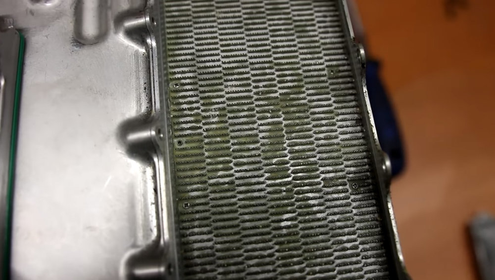
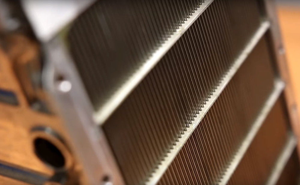
Old news, but the other engine threads had me thinking about the Ferrari intercooler design. From the photos made available last year, it's apparent that they used thousands of tiny coolant pipes for heat exchange. Supposedly ~16k of them, looking to be around 1mm OD. My initial impression was always that it looked like a heavy unit and was oddly located on the top of the engine. But I had not fully considered the design. It's mostly air by volume, the coolant volume is very low relative to air volume, and the aluminum housing is thinly machined. The surface-to-air ratio must be huge and I wonder if Merc's unit is similarly designed.

Some speculate about using 3D printing but I don't think you can get close to the surface-air ratio provided by thousands of non-porous extruded pipes. Porosity, thin wall strength, and surface texture would be superior with extruded tubes. Yes, surface roughness may help turbulence and heat exchange, but relative to the small channel sizes and thin walls required for extreme coolant-air ratios, it might just end up inhibiting flow and weakening the structure.

Regarding Merc, how else might you achieve such performance within such a small volume? Are they constrained to a similar approach?

Image

Image

Image

Image

Image

Image

hurril
hurril
54
Joined: 07 Oct 2014, 13:02

Re: Formula One 1.6l V6 turbo engine formula

Post

It's a thing of beauty!

User avatar
dren
226
Joined: 03 Mar 2010, 14:14

Re: Formula One 1.6l V6 turbo engine formula

Post

It sure is. I was always impressed by the Ferrari packaging of their early PU, even if it was quite down on power.
Honda!

User avatar
MrPotatoHead
53
Joined: 20 Apr 2017, 19:03
Location: All over.

Re: Formula One 1.6l V6 turbo engine formula

Post

This will explain a lot of it for you:

https://mezzotech.com/why-micro-tubes/

User avatar
godlameroso
309
Joined: 16 Jan 2010, 21:27
Location: Miami FL

Re: Formula One 1.6l V6 turbo engine formula

Post

According to this they can cool the intake charge below +10 degrees ambient, wonder if that's why the rules state IAT must be 10+ degrees above ambient. I wonder if they wanted a heat exchanger arms race because this is how you get one. If these intercoolers are that efficient, then they can be sized smaller and smaller in order to meet the 10+ ambient requirement. Which has obvious benefits.

They also say that using microtubes saves on cost because there's no welding, but I can't imagine these are cheap either.
Saishū kōnā

hurril
hurril
54
Joined: 07 Oct 2014, 13:02

Re: Formula One 1.6l V6 turbo engine formula

Post

godlameroso wrote:
10 Jan 2018, 19:33
According to this they can cool the intake charge below +10 degrees ambient, wonder if that's why the rules state IAT must be 10+ degrees above ambient. I wonder if they wanted a heat exchanger arms race because this is how you get one. If these intercoolers are that efficient, then they can be sized smaller and smaller in order to meet the 10+ ambient requirement. Which has obvious benefits.

They also say that using microtubes saves on cost because there's no welding, but I can't imagine these are cheap either.
How could they possibly cool to something below ambient? Is there a compressor involved?

User avatar
Zynerji
110
Joined: 27 Jan 2016, 16:14

Re: Formula One 1.6l V6 turbo engine formula

Post

hurril wrote:
10 Jan 2018, 19:51
godlameroso wrote:
10 Jan 2018, 19:33
According to this they can cool the intake charge below +10 degrees ambient, wonder if that's why the rules state IAT must be 10+ degrees above ambient. I wonder if they wanted a heat exchanger arms race because this is how you get one. If these intercoolers are that efficient, then they can be sized smaller and smaller in order to meet the 10+ ambient requirement. Which has obvious benefits.

They also say that using microtubes saves on cost because there's no welding, but I can't imagine these are cheap either.
How could they possibly cool to something below ambient? Is there a compressor involved?
Passive vortex tubes.

hurril
hurril
54
Joined: 07 Oct 2014, 13:02

Re: Formula One 1.6l V6 turbo engine formula

Post

Zynerji wrote:
10 Jan 2018, 19:55
hurril wrote:
10 Jan 2018, 19:51
godlameroso wrote:
10 Jan 2018, 19:33
According to this they can cool the intake charge below +10 degrees ambient, wonder if that's why the rules state IAT must be 10+ degrees above ambient. I wonder if they wanted a heat exchanger arms race because this is how you get one. If these intercoolers are that efficient, then they can be sized smaller and smaller in order to meet the 10+ ambient requirement. Which has obvious benefits.

They also say that using microtubes saves on cost because there's no welding, but I can't imagine these are cheap either.
How could they possibly cool to something below ambient? Is there a compressor involved?
Passive vortex tubes.
Do you think these coolers use that?

63l8qrrfy6
63l8qrrfy6
368
Joined: 17 Feb 2016, 21:36

Re: Formula One 1.6l V6 turbo engine formula

Post

Nah, its more likely that they use turboencabulators

mrluke
mrluke
33
Joined: 22 Nov 2013, 20:31

Re: Formula One 1.6l V6 turbo engine formula

Post

It says below +10 ambient. so for example ambient +5 degrees would comply. It doesn't mean that the charge is cooled below ambient temp.