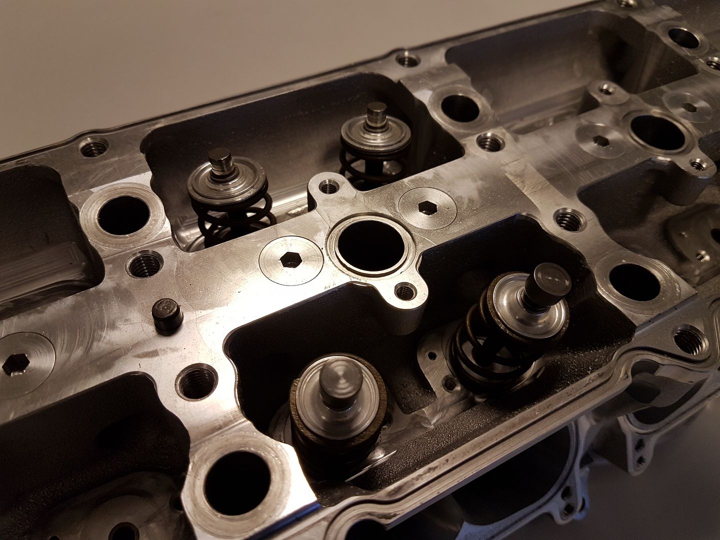
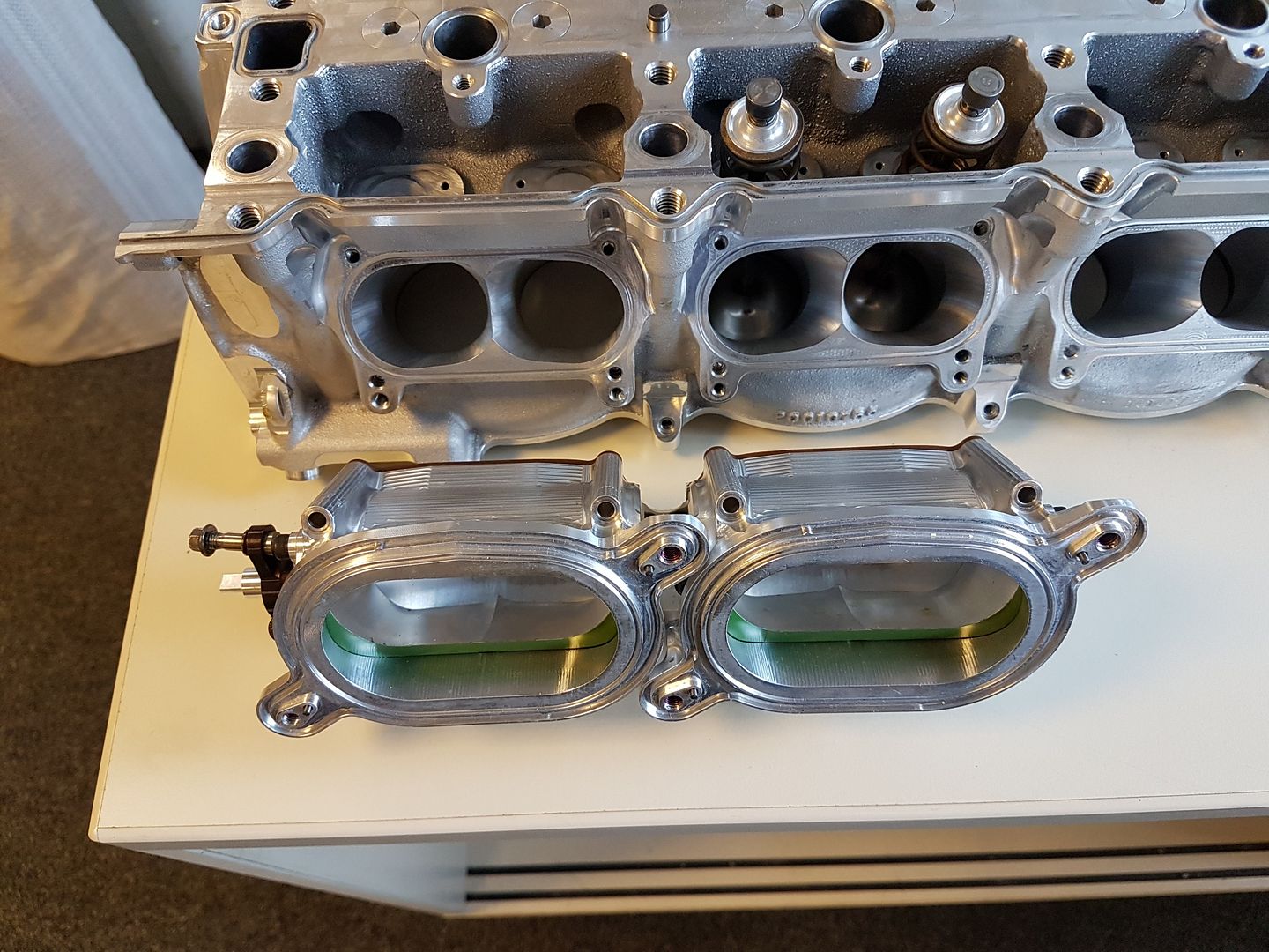
In this thread I will be unlocking a few secrets hidden within this part - the F1 V10 Intake Camshaft, mainly its features in terms of design, drive and oiling, and most importantly the lift numbers. It's from my own Cosworth F1 V10 TJ engine. This Engine was from the last of the V10's during 2005 and an important one since it is N/A, and has a high Redline - @ 19,000rpm.
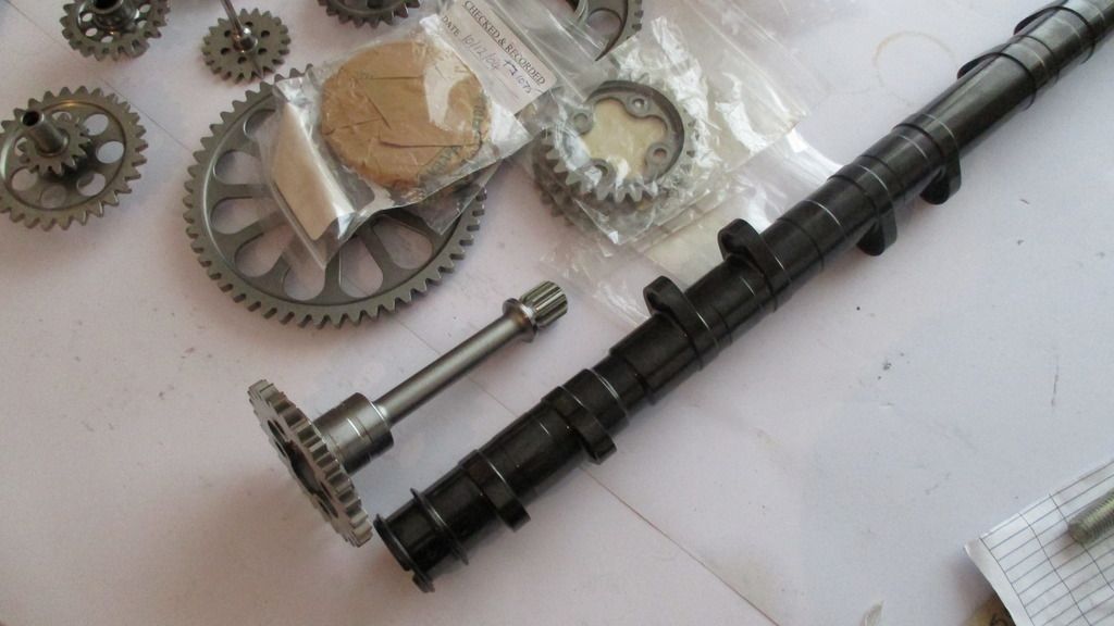
As some of you may know - the camshaft was driven with a quill shaft - this shaft acted as a torsion bar and in turn lessened fluctuations in angular velocity.
The DLC coated intake cam as well as the drive quill can be seen below.
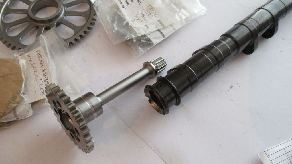
A close up of the quill splines as well as the hollow cam bore below that,
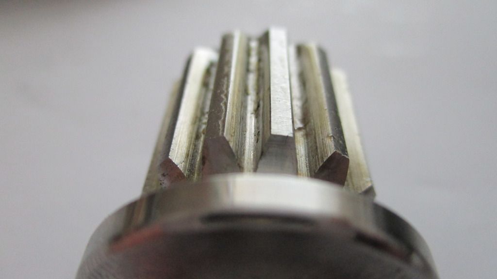

The valve actuation is via finger followers as shown below,

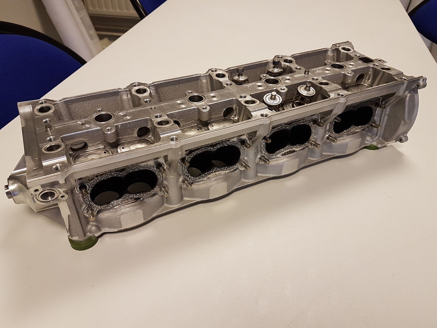
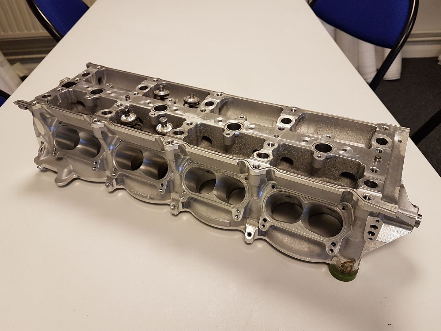
These bolt into pockets along the I-beam head,
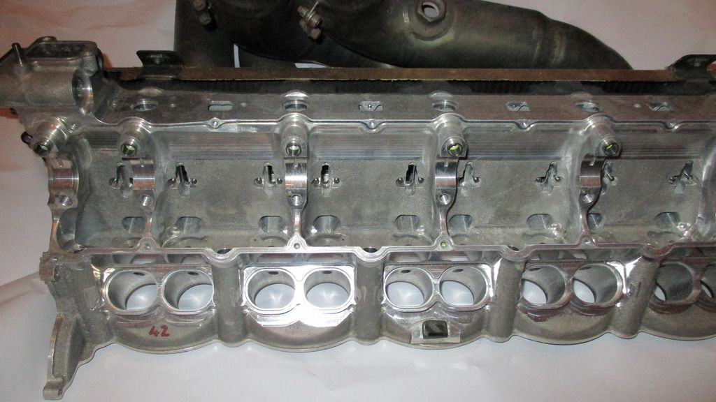
They are cooled with a jet(removed) that is screwed into a drilling above the follower pivot,

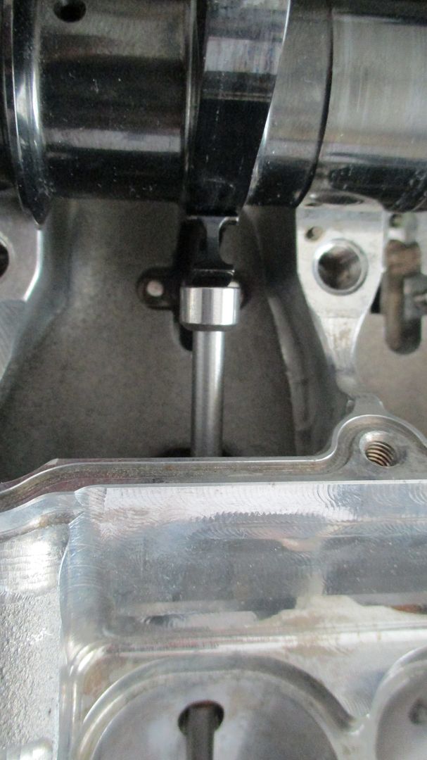
A shot of the cam and finger follower, as well as the mock valve stem used to take the lift measurements,
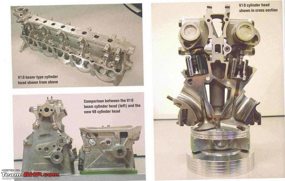
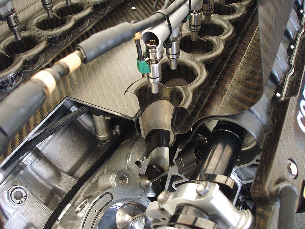
A cutaway of the TJ engine showing general layout,
The rig setup shown below used to take lift measurements,
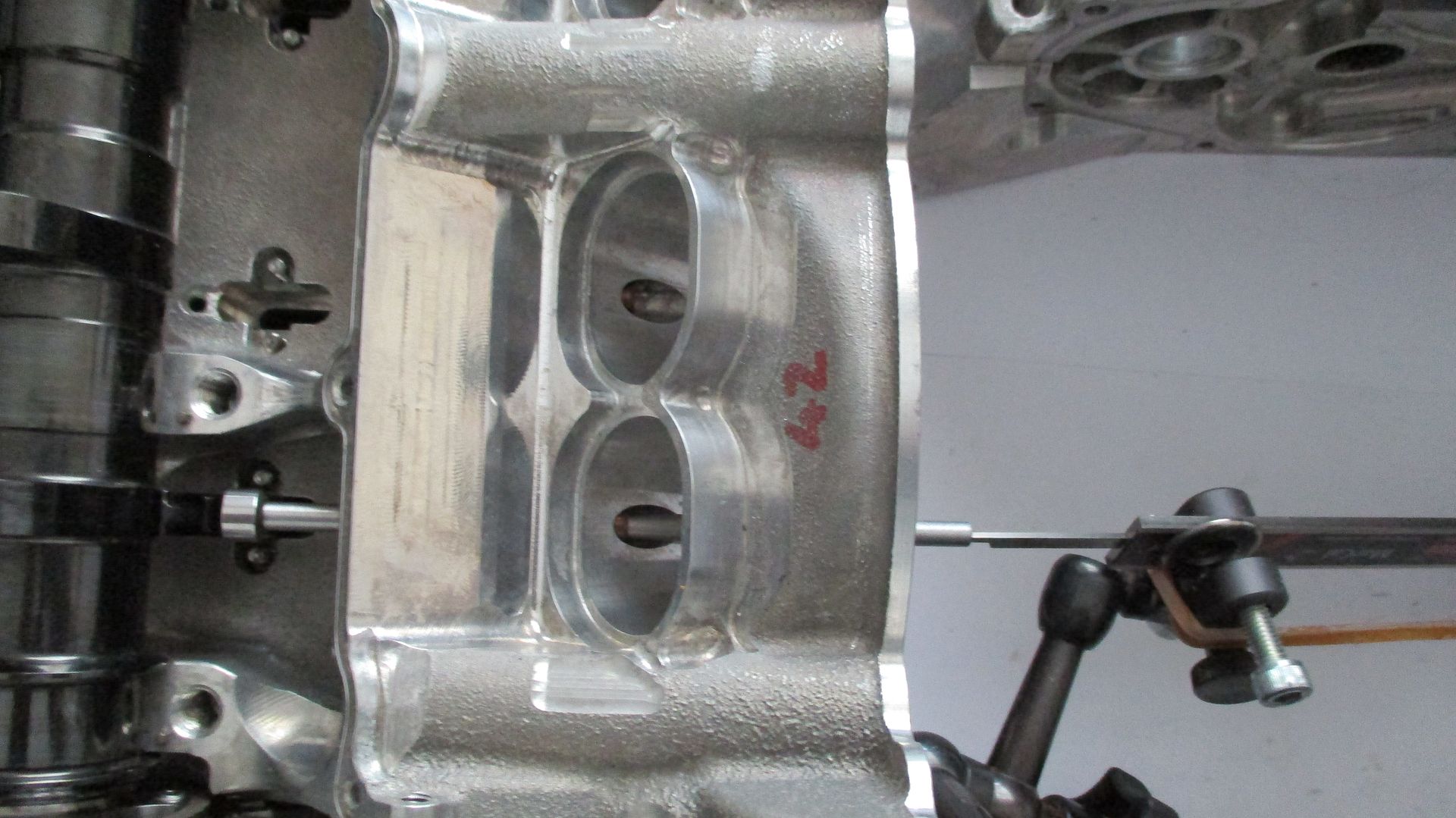
A MAHR wireless calipers was used to create the lift vs angle chart. The calipers has the nice feature of being wireless and can populate an excel sheet on command - which saves a lot of writing and possible errors.
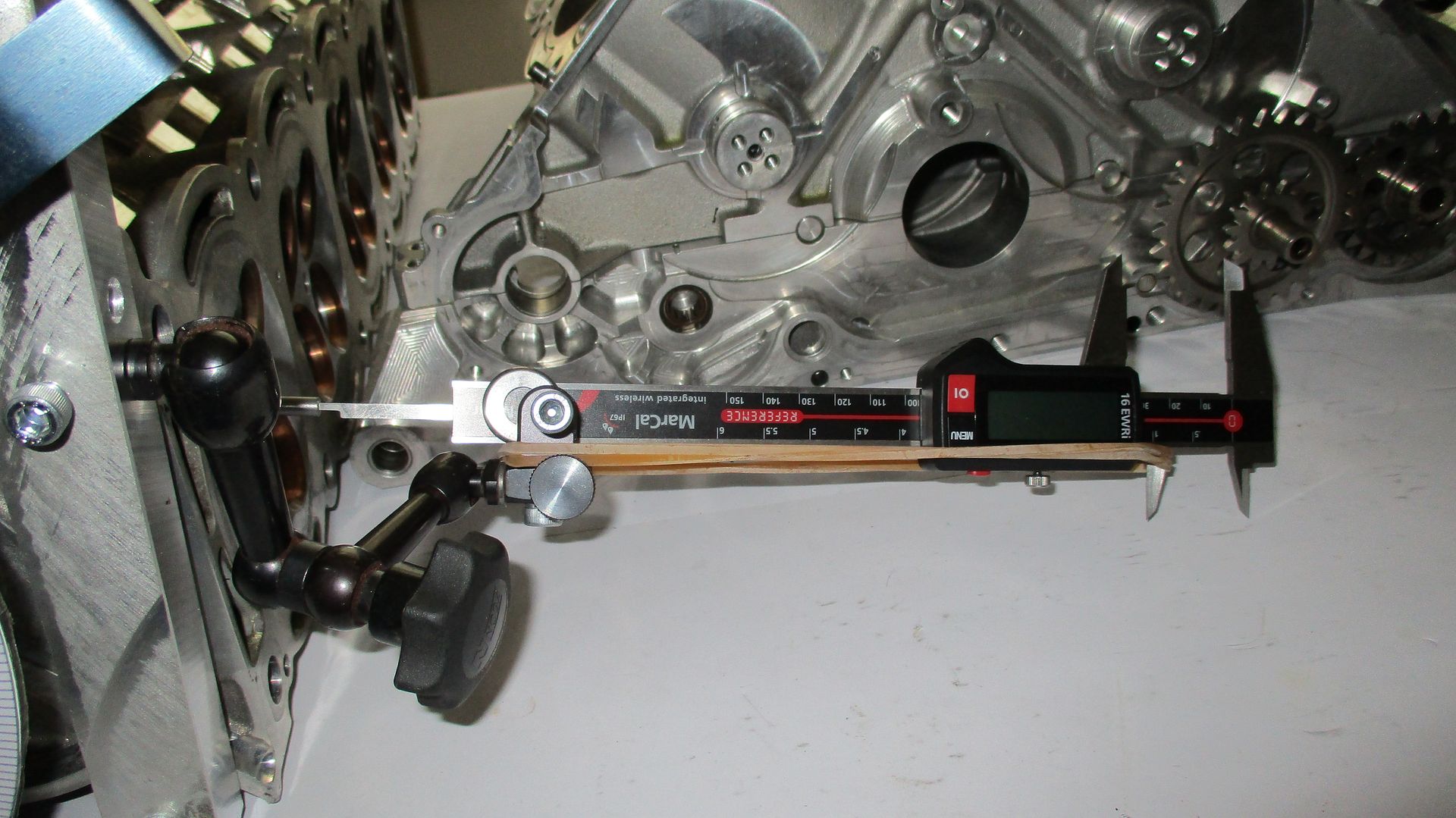
A 360 degree wheel was fixed to the end of the cam. The cam was then rotated to the points where it just started to lift the valve off seat(.01) and also to the point at which the valve came back on seat(0.00). The angular distance between these two points was then halved and this was the position TDC was assumed on the degree wheel. Please note, this may not be the actual TDC point of the engine but it did seem a good place to start taking measurements and in reality a better term would be lobe center line since max lift was seen at 180 degrees.
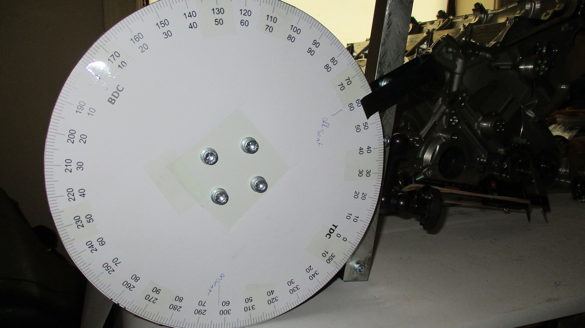
Some key measurements were noted -
Intake valve starts to open at 63 degrees after TDC (''off seat'' on degree wheel - wheel turns clockwise)
Intake valve comes back on seat at 298 degrees after TDC (''on seat'' on degree wheel - wheel turns clockwise)
Max lift - 15.95mm @180 Degrees after TDC.
The plotted graph -
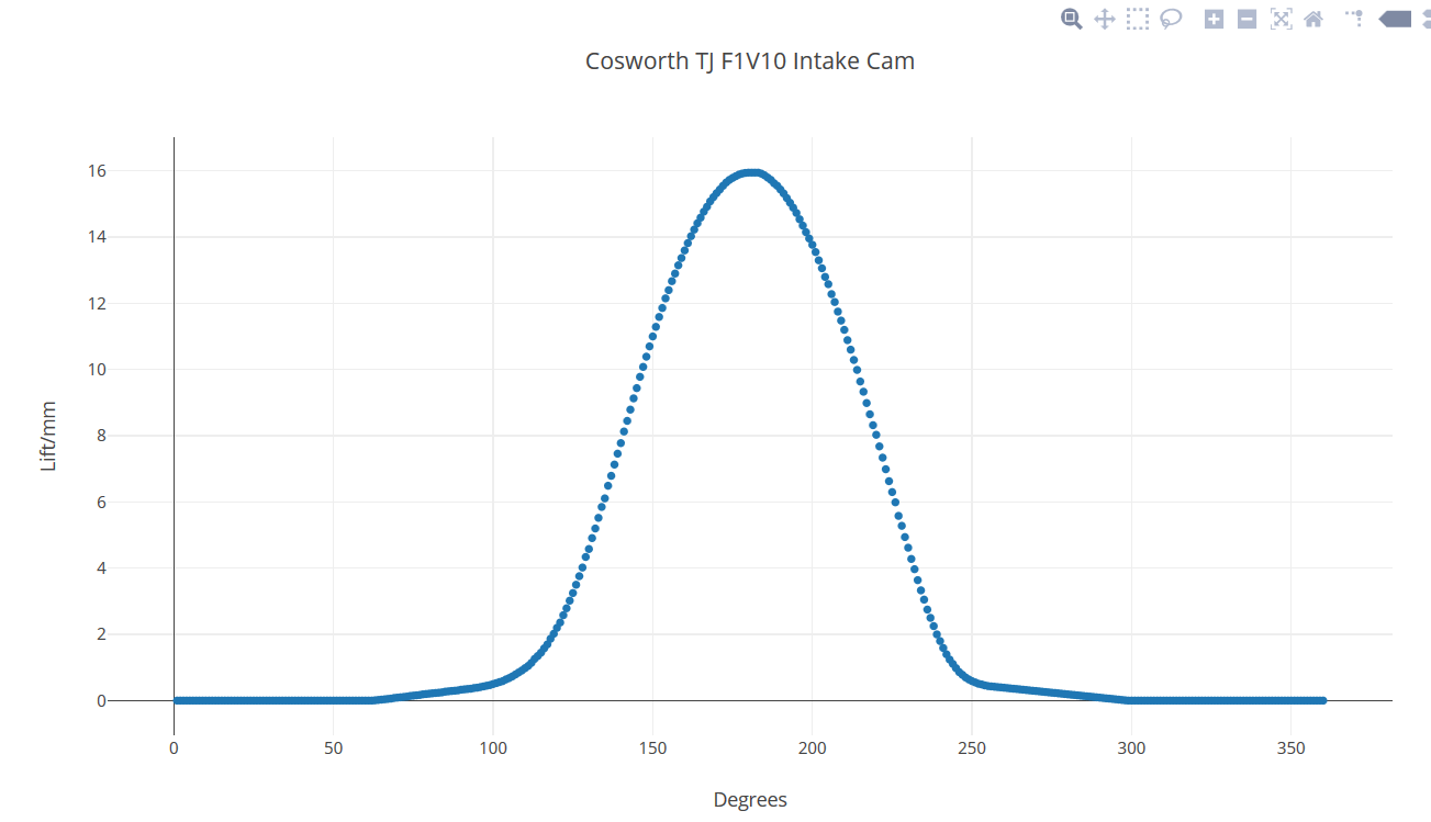
The lift dimensions are listed below for ease of copy and paste should anyone want to analyze the numbers in more detail - Vel, Acc, etc.
Please beware they are to be placed beside a cam angle list from 1-360 degrees.
0
0
0
0
0
0
0
0
0
0
0
0
0
0
0
0
0
0
0
0
0
0
0
0
0
0
0
0
0
0
0
0
0
0
0
0
0
0
0
0
0
0
0
0
0
0
0
0
0
0
0
0
0
0
0
0
0
0
0
0
0
0.01
0.02
0.03
0.04
0.05
0.06
0.08
0.09
0.1
0.11
0.12
0.14
0.15
0.16
0.17
0.19
0.2
0.21
0.22
0.23
0.24
0.25
0.27
0.28
0.29
0.3
0.31
0.33
0.34
0.35
0.36
0.38
0.39
0.41
0.43
0.45
0.47
0.5
0.53
0.56
0.59
0.64
0.68
0.73
0.79
0.85
0.91
0.98
1.05
1.14
1.26
1.35
1.45
1.58
1.7
1.87
2.02
2.2
2.36
2.58
2.79
3.02
3.25
3.5
3.76
4.02
4.34
4.58
4.91
5.2
5.52
5.85
6.11
6.49
6.79
7.13
7.46
7.78
8.13
8.45
8.79
9.13
9.44
9.78
10.08
10.39
10.7
11
11.29
11.59
11.86
12.15
12.4
12.67
12.9
13.15
13.37
13.6
13.82
14.03
14.23
14.42
14.59
14.77
14.92
15.08
15.21
15.33
15.44
15.55
15.65
15.73
15.79
15.84
15.89
15.92
15.94
15.95
15.95
15.95
15.95
15.92
15.87
15.8
15.73
15.63
15.55
15.44
15.32
15.18
15.04
14.89
14.73
14.54
14.35
14.15
13.96
13.77
13.55
13.3
13.06
12.8
12.58
12.28
12.04
11.75
11.48
11.2
10.89
10.6
10.29
9.99
9.64
9.33
8.99
8.65
8.32
8.03
7.68
7.34
6.99
6.63
6.3
5.99
5.58
5.28
4.94
4.62
4.28
3.97
3.64
3.33
3.05
2.75
2.5
2.25
2
1.8
1.59
1.4
1.24
1.11
0.98
0.86
0.78
0.7
0.64
0.59
0.55
0.51
0.49
0.46
0.44
0.43
0.42
0.41
0.4
0.39
0.38
0.37
0.36
0.35
0.34
0.33
0.32
0.31
0.3
0.29
0.28
0.27
0.26
0.25
0.24
0.23
0.22
0.21
0.2
0.19
0.18
0.17
0.16
0.15
0.14
0.13
0.12
0.11
0.1
0.09
0.08
0.07
0.06
0.05
0.04
0.03
0.02
0.01
0
0
0
0
0
0
0
0
0
0
0
0
0
0
0
0
0
0
0
0
0
0
0
0
0
0
0
0
0
0
0
0
0
0
0
0
0
0
0
0
0
0
0
0
0
0
0
0
0
0
0
0
0
0
0
0
0
0
0
0
0
0
Thats all for now - Enjoy,
Brian,


