- Login or Register
No account yet? Sign up

Formula One's governing body has announced that it has come to a settlement with Scuderia Ferrari after investigations into its 2019 power unit, considered the most powered in F1.

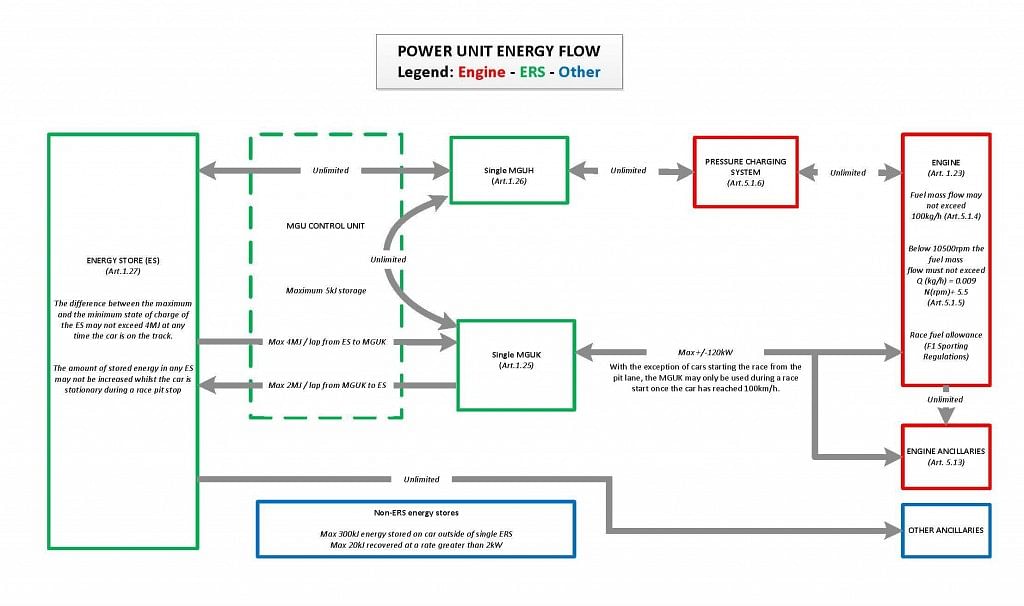
The official flow chart does not show that:saviour stivala wrote: ↑19 Jul 2018, 15:22With a mandated flow measuring sensor on the “K” that measures flow (IN) from the “K” to ERS components, and flow (OUT) from the “K” to the crankshaft. And the FIA official flow chart (link I posted) clearly marking flow from “K” IN and OUT as being LIMITTED, there is no way that these 2 flows can be more than that stipulated by the rules, it is useless suggesting flow routes and saying unlimited this and unlimited that because whatever is thrown at the “K” cannot pass IN or OUT OF the “K” any bigger than that permitted.

The fuel injection rule (must be direct injection) leaves no leeway for interpretation. The fuel injection must take place in the space above the piston. I know of no pre-combustion system were fuel and or spark doesn’t take place inside it/were combustion is not started inside it. A pre-combustion chamber of 10 cc or 1 cc is still a pre-combustion chamber. and Godlameroso, how can i think that there is a pre-combustion chamber being used in F1?godlameroso wrote: ↑19 Jul 2018, 14:12That's fair, do you think that there is no type of pre-chamber being used in F1?saviour stivala wrote: ↑19 Jul 2018, 09:26That’s a bit better, as you have bothered to respond. re you referring me to here and there, I have followed all you recommended when it happened. I have been involved in the TJI combustion system claim to being used in F1 from the beginning the original pusher pushed this grandee speculation out, that was actually after he first pushed out the use of HCCI, and when on his forum I asked him if he believes a system that requires VVT and more than one injector was compatible with F1 rules, he first went to ANDY COWELL asking if they are using it, and when told no, he came out and said that it was not HCCI that was being used but TJI (his words), when again I asked him if he considers TJI that containing an injector and spark plug in a pre-combustion chamber and injecting and igniting the charge in a pre-combustion chamber was compatible with the direct injection rules, his answer was very simple, I was blocked from on his forum. We are here talking about what is regarded as a top notch F1 technical advisor to a popular broadcaster. My opinion to this day, and that is now some years after Mahle TJI combustion system was pushed out as being used in F1 is still the same as back then, it is not compatible with F1 rules. If a system of similar principle but still starts combustion in a pre-combustion chamber is claimed of being in use, I am still of the opinion that such a system is not compatible with rules.
What do you think of this bit of the regulations?
5.1.11 An insert within a PU component is a minimal, non-dismountable part whose function is solely to locally support a function of this component. The total volume of inserts within the component cannot be more than 10% of the total volume of the component.
Doesn't this sort of pre-suppose that there's a pre-chamber? If I'm reading this right it's saying that the pre-chamber is limited to 10% of the CC volume?
There's a lot of questions I probably won't get the answers to.
The official flow chart you show show unlimitted flow from "H" to "K" but it also shows a limitted max of 120kw from "k" to cranckshaft. to see it more clearly google "fia 2014 formula one power unit regulations" scroll down to "power unit energy flow legend engine ERS car (flow chart)". and see for yourself that "K" IN and OUT flow is limmited regardless what is thrown at it unlimitted.turbof1 wrote: ↑19 Jul 2018, 15:40The official flow chart does not show that:saviour stivala wrote: ↑19 Jul 2018, 15:22With a mandated flow measuring sensor on the “K” that measures flow (IN) from the “K” to ERS components, and flow (OUT) from the “K” to the crankshaft. And the FIA official flow chart (link I posted) clearly marking flow from “K” IN and OUT as being LIMITTED, there is no way that these 2 flows can be more than that stipulated by the rules, it is useless suggesting flow routes and saying unlimited this and unlimited that because whatever is thrown at the “K” cannot pass IN or OUT OF the “K” any bigger than that permitted.
http://static.sportskeeda.com/wp-conten ... 24x606.jpg
Energy transfer between K and H is stated to be unlimited. And between ES and H is also unlimited. If we were naïve individuals, based on this flow chart you could say "screw ES to K, I am just going to use ES to H to K which is unlimited". Again this is surely not happening, but it's not because of the presented flow chart.
Again what the sensor measure is not enough on its own as a limiting regulation. You can hang a sensor of how much time the driver waves to the public, but I'd still need a regulation to limit his waves to 5 times each race. The sensors you are putting forward surely measure up to ensure everybody is keeping to the regulations; that's not the point of debate here. The point is: the regulation that forbids K generated and stored energy to be unlimited used through the H unit is not on the flow chart and not in the technical regulations. Others have debated this is effectively a possibility; I myself think "yeah, this is in a technical directive probably even before 2014".
2 remarks on that:saviour stivala wrote: ↑19 Jul 2018, 16:03The official flow chart you show show unlimitted flow from "H" to "K" but it also shows a limitted max of 120kw from "k" to cranckshaft. to see it more clearly google "fia 2014 formula one power unit regulations" scroll down to "power unit energy flow legend engine ERS car (flow chart)". and see for yourself that "K" IN and OUT flow is limmited regardless what is thrown at it unlimitted.turbof1 wrote: ↑19 Jul 2018, 15:40The official flow chart does not show that:saviour stivala wrote: ↑19 Jul 2018, 15:22With a mandated flow measuring sensor on the “K” that measures flow (IN) from the “K” to ERS components, and flow (OUT) from the “K” to the crankshaft. And the FIA official flow chart (link I posted) clearly marking flow from “K” IN and OUT as being LIMITTED, there is no way that these 2 flows can be more than that stipulated by the rules, it is useless suggesting flow routes and saying unlimited this and unlimited that because whatever is thrown at the “K” cannot pass IN or OUT OF the “K” any bigger than that permitted.
http://static.sportskeeda.com/wp-conten ... 24x606.jpg
Energy transfer between K and H is stated to be unlimited. And between ES and H is also unlimited. If we were naïve individuals, based on this flow chart you could say "screw ES to K, I am just going to use ES to H to K which is unlimited". Again this is surely not happening, but it's not because of the presented flow chart.
Again what the sensor measure is not enough on its own as a limiting regulation. You can hang a sensor of how much time the driver waves to the public, but I'd still need a regulation to limit his waves to 5 times each race. The sensors you are putting forward surely measure up to ensure everybody is keeping to the regulations; that's not the point of debate here. The point is: the regulation that forbids K generated and stored energy to be unlimited used through the H unit is not on the flow chart and not in the technical regulations. Others have debated this is effectively a possibility; I myself think "yeah, this is in a technical directive probably even before 2014".
I am not 100% sure what you mean with this. If you are suggesting that the ES-K energy exchange limits apply on the H-K energy exchange limits, then they don't based on the flow chart. If you mean something else, then do please clarify.see for yourself that "K" IN and OUT flow is limmited regardless what is thrown at it unlimitted.
There is no sensor between the MGUK and the crankshaft.saviour stivala wrote: ↑19 Jul 2018, 15:22With a mandated flow measuring sensor on the “K” that measures flow (IN) from the “K” to ERS components, and flow (OUT) from the “K” to the crankshaft. And the FIA official flow chart (link I posted) clearly marking flow from “K” IN and OUT as being LIMITTED, there is no way that these 2 flows can be more than that stipulated by the rules, it is useless suggesting flow routes and saying unlimited this and unlimited that because whatever is thrown at the “K” cannot pass IN or OUT OF the “K” any bigger than that permitted.


I’m not sure you understand.saviour stivala wrote: ↑19 Jul 2018, 10:12It doesnt matter, there is nothing hidden, that's the same as "spiritopronto"henry wrote: ↑19 Jul 2018, 10:03That’s an interesting use of language there. Don’t try to be too clever or you’ll give the game away.saviour stivala wrote: ↑18 Jul 2018, 23:32
Good one that henry, you responded to my post on this here discussion forum and said what you had to say, but pronto and tipo spinto declares "no further discussion required".

How else would the be achieving such combustion efficiency? Again I don't know what combustion tricks they're using. It could be just as you say, a conventional direct injector over the piston crown with a spark plug next to it. Honda for a fact placed their injector on the exhaust side of the head, Mercedes perhaps as well.saviour stivala wrote: ↑19 Jul 2018, 15:50The fuel injection rule (must be direct injection) leaves no leeway for interpretation. The fuel injection must take place in the space above the piston. I know of no pre-combustion system were fuel and or spark doesn’t take place inside it/were combustion is not started inside it. A pre-combustion chamber of 10 cc or 1 cc is still a pre-combustion chamber. and Godlameroso, how can i think that there is a pre-combustion chamber being used in F1?godlameroso wrote: ↑19 Jul 2018, 14:12That's fair, do you think that there is no type of pre-chamber being used in F1?saviour stivala wrote: ↑19 Jul 2018, 09:26That’s a bit better, as you have bothered to respond. re you referring me to here and there, I have followed all you recommended when it happened. I have been involved in the TJI combustion system claim to being used in F1 from the beginning the original pusher pushed this grandee speculation out, that was actually after he first pushed out the use of HCCI, and when on his forum I asked him if he believes a system that requires VVT and more than one injector was compatible with F1 rules, he first went to ANDY COWELL asking if they are using it, and when told no, he came out and said that it was not HCCI that was being used but TJI (his words), when again I asked him if he considers TJI that containing an injector and spark plug in a pre-combustion chamber and injecting and igniting the charge in a pre-combustion chamber was compatible with the direct injection rules, his answer was very simple, I was blocked from on his forum. We are here talking about what is regarded as a top notch F1 technical advisor to a popular broadcaster. My opinion to this day, and that is now some years after Mahle TJI combustion system was pushed out as being used in F1 is still the same as back then, it is not compatible with F1 rules. If a system of similar principle but still starts combustion in a pre-combustion chamber is claimed of being in use, I am still of the opinion that such a system is not compatible with rules.
What do you think of this bit of the regulations?
5.1.11 An insert within a PU component is a minimal, non-dismountable part whose function is solely to locally support a function of this component. The total volume of inserts within the component cannot be more than 10% of the total volume of the component.
Doesn't this sort of pre-suppose that there's a pre-chamber? If I'm reading this right it's saying that the pre-chamber is limited to 10% of the CC volume?
There's a lot of questions I probably won't get the answers to.
I did not say there is a sensor between "K" and crankshaft, i said there is a sensor on the "k" that measure flow out of MGU-K either out to crankshaft or in to ERS components. and this measuring sensor will register if the limitted flow imposed by the regulations are not being broken.wuzak wrote: ↑19 Jul 2018, 16:52There is no sensor between the MGUK and the crankshaft.saviour stivala wrote: ↑19 Jul 2018, 15:22With a mandated flow measuring sensor on the “K” that measures flow (IN) from the “K” to ERS components, and flow (OUT) from the “K” to the crankshaft. And the FIA official flow chart (link I posted) clearly marking flow from “K” IN and OUT as being LIMITTED, there is no way that these 2 flows can be more than that stipulated by the rules, it is useless suggesting flow routes and saying unlimited this and unlimited that because whatever is thrown at the “K” cannot pass IN or OUT OF the “K” any bigger than that permitted.
A sensor measures the power going to, or out of, the MGUK (Volts and Amps) in the electrical circuit. An efficiency factor 95% for the electrical power to the MGUK means that a more efficient motor will give a few more hp (if it is 98% then the MGUK will deliver approximately 5hp more than the nominal amount).
The MGUK is mechanically fixed to the crankshaft, so no need to measure power there.
The sensor (probably bi-directional current sensor) will be placed between ES and MGU-K not between MGU-K and MGU-H as you won't be able to distinguish the flow from ES to MGU-K and vice versa.saviour stivala wrote: ↑19 Jul 2018, 18:24I did not say there is a sensor between "K" and crankshaft, i said there is a sensor on the "k" that measure flow out of MGU-K either out to crankshaft or in to ERS components. and this measuring sensor will register if the limitted flow imposed by the regulations are not being broken.wuzak wrote: ↑19 Jul 2018, 16:52There is no sensor between the MGUK and the crankshaft.saviour stivala wrote: ↑19 Jul 2018, 15:22With a mandated flow measuring sensor on the “K” that measures flow (IN) from the “K” to ERS components, and flow (OUT) from the “K” to the crankshaft. And the FIA official flow chart (link I posted) clearly marking flow from “K” IN and OUT as being LIMITTED, there is no way that these 2 flows can be more than that stipulated by the rules, it is useless suggesting flow routes and saying unlimited this and unlimited that because whatever is thrown at the “K” cannot pass IN or OUT OF the “K” any bigger than that permitted.
A sensor measures the power going to, or out of, the MGUK (Volts and Amps) in the electrical circuit. An efficiency factor 95% for the electrical power to the MGUK means that a more efficient motor will give a few more hp (if it is 98% then the MGUK will deliver approximately 5hp more than the nominal amount).
The MGUK is mechanically fixed to the crankshaft, so no need to measure power there.
I cannot for the life of me think that anybody outside of a “very very selective few” in each of the 4 teams big engine departments will ever know the details of their respective combustion process. Godlameroso, do you remember the past 1.5l turbo era?. the 2 most important thing that is making the difference between than and now are (1) fuel developments, and (2) "TOOLS" in the form of in-cylinder sensors that can control with some reliability abusing all combustion parameters to a very fine and delegate line between a big bang and success.godlameroso wrote: ↑19 Jul 2018, 17:28How else would the be achieving such combustion efficiency? Again I don't know what combustion tricks they're using. It could be just as you say, a conventional direct injector over the piston crown with a spark plug next to it. Honda for a fact placed their injector on the exhaust side of the head, Mercedes perhaps as well.saviour stivala wrote: ↑19 Jul 2018, 15:50The fuel injection rule (must be direct injection) leaves no leeway for interpretation. The fuel injection must take place in the space above the piston. I know of no pre-combustion system were fuel and or spark doesn’t take place inside it/were combustion is not started inside it. A pre-combustion chamber of 10 cc or 1 cc is still a pre-combustion chamber. and Godlameroso, how can i think that there is a pre-combustion chamber being used in F1?godlameroso wrote: ↑19 Jul 2018, 14:12
That's fair, do you think that there is no type of pre-chamber being used in F1?
What do you think of this bit of the regulations?
5.1.11 An insert within a PU component is a minimal, non-dismountable part whose function is solely to locally support a function of this component. The total volume of inserts within the component cannot be more than 10% of the total volume of the component.
Doesn't this sort of pre-suppose that there's a pre-chamber? If I'm reading this right it's saying that the pre-chamber is limited to 10% of the CC volume?
There's a lot of questions I probably won't get the answers to.
What kind of combustion process do you think Ferrari is using? Do you think just bumping up the compression ratio is enough?