Using intermediate components to exceed 4MJ per lap energy transfer between ES and MGUK

All that has to do with the power train, gearbox, clutch, fuels and lubricants, etc. Generally the mechanical side of Formula One.
User avatar
Red Rock Mutley
11
Joined: 28 Jul 2018, 17:04

Using intermediate components to exceed 4MJ per lap energy transfer between ES and MGUK

Post

I'm interested in a technical discussion on using the "unlimited" paths in the Power Unit Energy Flow diagram in the current F1 technical regs to increase the amount of per-lap energy available for transfer between the ES and MGU-K.

Obviously the direct path between ES and MGUK is limited to 4 and 2MJ per lap, however, there appears to be the possibility of adding to the amount of energy available by transferring energy via intermediate components. In the case of the MGU-H pathways, the energy is unlimited.

The MGUH is permitted to flow unlimited energy between it and the ES and also unlimited energy between it and the MGUK. If the MGU-H can be used as an energy transfer device, it appears permissible to make a path between the ES and MGU-K (by shuffling power via the MGU-H)

To my mind, there are (at least) 3 ways of using the MGU-H as an energy transfer device:
1: Treat the MGU-H as a black box with seperate electrical inputs and output. Internally connect the 2 wires, perhaps selectively. Without regulation of the internal power flow within the MGU-H, there seems little to prevent a simple diversion of power from electrical input to electrical output
2: Use the MGU-H as a kinetic converter of energy. Drive the MGU-H in electric supercharger mode by using energy from the ES to accelerate the turbine, then switching to generator mode and direct the recovered electrical energy to the MGU-K. I believe Honda use this mode
3: Use the MGU-H as a magnetic converter of energy. In much the same way as a dc-dc converter, power the windings within the MGU-H to create a magnetic field, then collapse the field to generate electricity. As an electrical engineer, this would be my prefered method - essentially the MGU-H becomes a very large flyback converter; of which efficiencies are typically high

User avatar
nzjrs
60
Joined: 07 Jan 2015, 11:21
Location: Redacted

Re: Using intermediate components to exceed 4MJ per lap energy transfer between ES and MGUK

Post

This has been discussed at length in other threads for more than a year. In the Honda PU threads and now more recently the Ferrari PU one.

saviour stivala
saviour stivala
48
Joined: 25 Apr 2018, 12:54

Re: Using intermediate components to exceed 4MJ per lap energy transfer between ES and MGUK

Post

nzjrs wrote:
29 Jul 2018, 07:02
This has been discussed at length in other threads for more than a year. In the Honda PU threads and now more recently the Ferrari PU one.
Correct, it’s obvious that he misses out the fact of the placement of the two FIA specified in-out energy measuring sensors placed as per the FIA on ERS elements whose in-out energy is restricted as per the FIA.

User avatar
Red Rock Mutley
11
Joined: 28 Jul 2018, 17:04

Re: Using intermediate components to exceed 4MJ per lap energy transfer between ES and MGUK

Post

I've seen some of those discussions, but it's difficult to get through the non-technical arguments. I suppose that's the pitfall of asking for a technical discussion on the internet. Before I reply, let me first post the relevant part of the FIA F1 technical regulation


------


ARTICLE 1: DEFINITIONS
1.24 Energy Recovery System (ERS) : A system that is designed to recover energy from the car, store that energy and make it available to propel the car and, optionally, to drive any ancillaries and actuation systems necessary for its proper function.
1.25 Motor Generator Unit - Kinetic (MGU-K) : The Kinetic Motor Generator Unit is the electrical machine mechanically linked to the drive train as part of the ERS.
1.26 Motor Generator Unit - Heat (MGU-H) : The Heat Motor Generator Unit is the electrical machine linked to the exhaust turbine of a pressure charging system as part of the ERS. 1.27 Energy Store (ES) : The part of ERS that stores energy, including its safety control electronics and a minimal housing.
...
ARTICLE 5 : POWER UNIT
5.1 Engine specification :
...
5.1.6 Pressure charging may only be effected by the use of a sole single stage compressor linked to a sole single stage exhaust turbine by a shaft assembly parallel to the engine crankshaft and within 25mm of the car centre plane. The shaft must be designed so as to ensure that the shaft assembly, the compressor and the turbine always rotate about a common axis and at the same angular velocity, an electrical motor generator (MGU-H) may be directly coupled to it. The shaft may not be mechanically linked to any other device.
...
5.2.1 The use of any device, other than the engine described in 5.1 above, and one MGU-K, to propel the car, is not permitted.
5.2.2 Energy flows, power and ES state of charge limits are defined in the energy flow diagram shown in Appendix 3 of these regulations.
When the car is on the track a lap will be measured on each successive crossing of the timing line, however, when entering the pits the lap will end, and the next one will begin, at the start of the pit lane (as defined in the F1 Sporting Regulations).
Electrical DC measurements will be used to verify that the energy and power requirements are being respected. A fixed efficiency correction of 0.95 will be used to monitor the maximum MGU-K power.
5.2.3 The MGU-K must be solely and permanently mechanically linked to the powertrain before the main clutch. This mechanical link must be of fixed speed ratio to the engine crankshaft.
The rotational speed of the MGU-K may not exceed 50,000rpm.
The weight of the MGU-K (as defined in line 11 of Appendix 2 to these regulations) may not be less than 7kg. The maximum torque of the MGU-K may not exceed 200Nm.
The torque will be referenced to the crankshaft speed and the fixed efficiency correction defined in Article 5.2.2 will be used to monitor the maximum MGU-K torque. The laminate thickness of the MGU-K may not be less than 0.05mm.
5.2.4 The MGU-H must be solely mechanically linked to the pressure charging system. This mechanical link must be of fixed speed ratio to the exhaust turbine and may be clutched.
The rotational speed of the MGU-H may not exceed 125,000rpm.
The weight of the MGU-H (as defined in line 13 of Appendix 2 to these regulations) may not be less than 4kg.
5.2.5 Cars must be fitted with homologated sensors which provide all necessary signals to the FIA data logger in order to verify the requirements above are being respected.

5.12 Energy Recovery System (ERS) :

5.12.6 All elements of the power unit specified in Article 5.12.7 must be installed wholly within the survival cell.
The total weight of these elements (The weight considered is the sum of the individual weights of these elements) must be greater than the minimum weight of the same elements determined between all the homologated power units at the start of the 2017 season.
The volume occupied by these elements (The volume considered is the sum of the individual volumes occupied by these elements) must be greater than the minimum volume of the same elements determined between all the homologated power units at the start of the 2017 season.
5.12.7 The elements of the power unit that are considered for Article 5.12.6 are :
a) ES elements as defined in lines 16 and 17 of Appendix 2 to these regulations.
b) Any DC-DC converter connected to ES HV DC bus. Includes active parts, enclosure, brackets and supports.
c) CU-K (MGU-K control unit). Includes active parts, enclosure, brackets and supports.
d) CU-H (MGU-H control unit). Includes active parts, enclosure, brackets and supports.
e) HV DC connections between ES and CU-K/CU-H/DC-DC converter. Includes all conductors, insulation, EMC screening, mechanical and thermal shielding.

User avatar
Red Rock Mutley
11
Joined: 28 Jul 2018, 17:04

Re: Using intermediate components to exceed 4MJ per lap energy transfer between ES and MGUK

Post

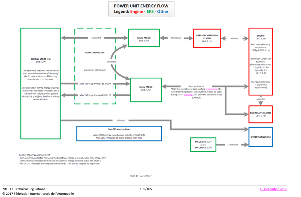
And the Appendix 3 Power Unit Energy Flow diagram

Image
Last edited by Red Rock Mutley on 02 Aug 2018, 23:53, edited 1 time in total.

User avatar
henry
324
Joined: 23 Feb 2004, 20:49
Location: England

Re: Using intermediate components to exceed 4MJ per lap energy transfer between ES and MGUK

Post

Red Rock Mutley wrote:
29 Jul 2018, 10:20
I've seen some of those discussions, but it's difficult to get through the non-technical arguments. I suppose that's the pitfall of asking for a technical discussion on the internet. Before I reply, let me first post the relevant part of the FIA F1 technical regulation
You need to add to your list of regulations the energy flow diagram, and in particular the note that there are just 2 sensors measuring all the flows in and out of the ES and K.

Do determine if flow from one sensor arrived at the other directly I think there must be some time constraint. Any flows, in direction and magnitude, happening “simultaneously” will be counted towards the flow control restrictions.

So in harvest mode your original 2 methods require the K to generate for a while, the result to be stored, kinetically or electrically, and then the K switches off and the stored energy goes to the ES while the K sensor is quiescent.

Honda do this at 20 to 40hz. So with 120kW symmetrical flow that’s an H fluctuation of the order of 2500 to 5000 rpm, or a 1.5 to 3.0 kJ storage in the CU.

The key to this is that the K sensor is seeing no flow while the ES sensor sees a flow.

I don’t know if your magnetic solution could perform in this way.

There are issues around H duty cycle since in harvest at the end of the straight it would be producing its own contribution whilst diverting the K contribution, peaks of 180kW or even more depending on the on-off cycle.
Fortune favours the prepared; she has no favourites and takes no sides.
Truth is confirmed by inspection and delay; falsehood by haste and uncertainty : Tacitus

User avatar
Red Rock Mutley
11
Joined: 28 Jul 2018, 17:04

Re: Using intermediate components to exceed 4MJ per lap energy transfer between ES and MGUK

Post

henry wrote:
29 Jul 2018, 11:08
You need to add to your list of regulations the energy flow diagram, and in particular the note that there are just 2 sensors measuring all the flows in and out of the ES and K.
I did post it, but unfortunately it requires moderator approval. I'm a long time lurker / new poster. Normally I steer clear of posting to the forums, but with a background in engineering and writing regulations for motorsport, this issue has me intrigued

User avatar
Red Rock Mutley
11
Joined: 28 Jul 2018, 17:04

Re: Using intermediate components to exceed 4MJ per lap energy transfer between ES and MGUK

Post

henry wrote:
29 Jul 2018, 11:08
...in particular the note that there are just 2 sensors measuring all the flows in and out of the ES and K.

Do determine if flow from one sensor arrived at the other directly I think there must be some time constraint. Any flows, in direction and magnitude, happening “simultaneously” will be counted towards the flow control restrictions
That's an interesting point. It doesn't seem possible to measure the transfer of energy between the MGU-K and the ES with those 2 sensors. Looking at just the ES, the reg says " One sensor is connected to measure all the electrical energy in/out of the Energy Store". A quick look at the energy flow diagram reveals multiple flow paths of energy in and out of the ES. It doesn't seem possible to seperate the flows using 1 sensor; by definition the flows are combined (summed) before entering and exiting the sensor. More than that, as 2 of the flow paths are marked "unlimited", the total permissible flow in and out of the energy store is similarly "unlimited". So whilst the energy flow can be measured, it doesn't seem possible to separate out the different energy flow paths. And consequently it doesn't seem possible to regulate the 2/4MJ per lap energy transfer limit between the ES and MGU-K

Those sensors are useful in regulating other parts of Appendix 3. Given the ES sensor measures total energy flow in and out, it can regulate the 4MJ limit in difference between the minimum and maximum state of charge of the ES. While the MGU-K sensor can measure the power output of the MGU-K

User avatar
henry
324
Joined: 23 Feb 2004, 20:49
Location: England

Re: Using intermediate components to exceed 4MJ per lap energy transfer between ES and MGUK

Post

Red Rock Mutley wrote:
29 Jul 2018, 12:55
henry wrote:
29 Jul 2018, 11:08
...in particular the note that there are just 2 sensors measuring all the flows in and out of the ES and K.

Do determine if flow from one sensor arrived at the other directly I think there must be some time constraint. Any flows, in direction and magnitude, happening “simultaneously” will be counted towards the flow control restrictions
That's an interesting point. It doesn't seem possible to measure the transfer of energy between the MGU-K and the ES with those 2 sensors. Looking at just the ES, the reg says " One sensor is connected to measure all the electrical energy in/out of the Energy Store". A quick look at the energy flow diagram reveals multiple flow paths of energy in and out of the ES. It doesn't seem possible to seperate the flows using 1 sensor; by definition the flows are combined (summed) before entering and exiting the sensor. More than that, as 2 of the flow paths are marked "unlimited", the total permissible flow in and out of the energy store is similarly "unlimited". So whilst the energy flow can be measured, it doesn't seem possible to separate out the different energy flow paths. And consequently it doesn't seem possible to regulate the 2/4MJ per lap energy transfer limit between the ES and MGU-K

Those sensors are useful in regulating other parts of Appendix 3. Given the ES sensor measures total energy flow in and out, it can regulate the 4MJ limit in difference between the minimum and maximum state of charge of the ES. While the MGU-K sensor can measure the power output of the MGU-K
So how do you think they differentiate the unlimited flows from those that are constrained?

As I said above my supposition is that the counter(s) are synchronised in some way.

So if in a measuring period 3kJ is measured leaving the ES and 2kJ is measured arriving at the K the supposition is that 1kJ went to the H.

The implications are that there is a tacit assumption that the H never sends or receives energy simultaneously from the ES and K.

When I apply that to the extra-harvest scenario it means that when the K is sending energy to the H the H cannot simultaneously send to the ES since that would seem to the sensors as direct flow from K to ES. I hadn’t spotted that before.
Fortune favours the prepared; she has no favourites and takes no sides.
Truth is confirmed by inspection and delay; falsehood by haste and uncertainty : Tacitus

PhillipM
PhillipM
386
Joined: 16 May 2011, 15:18
Location: Over the road from Boothy...

Re: Using intermediate components to exceed 4MJ per lap energy transfer between ES and MGUK

Post

Which may be why the FIA had to put extra software on Ferrari's car to check they were doing it legally at the time.

User avatar
Red Rock Mutley
11
Joined: 28 Jul 2018, 17:04

Re: Using intermediate components to exceed 4MJ per lap energy transfer between ES and MGUK

Post

henry wrote:
29 Jul 2018, 11:08
...supposition is that the counter(s) are synchronised in some way.

So if in a measuring period 3kJ is measured leaving the ES and 2kJ is measured arriving at the K the supposition is that 1kJ went to the H.

The implications are that there is a tacit assumption that the H never sends or receives energy simultaneously from the ES and K...

It's interesting to follow your example through as presumably the Honda method goes down that route. Let for sake of argument say the measurement period is synchronised with the cycling of the MGU-H between consuming power and generating power, and the MGU-K is kept at a constant power:

The first measurement period would follow your description – 3 kJ out of the ES, 2 kJ in to the MGU-K, the remaining 1 kJ is used to power the MGU-H in motor mode (spin it up). All that's non-controversial – the per-lap total energy transfer ES to MGU-K increases up by 2kJ during this period

In the second measurement period the MGU-H switches to generator mode (harvest) and recovers what it can of the 1 kJ input energy. Let's say it's perfect, so 1kJ is recovered from the MGU-H and flows through the MGU-H to MGU-K path. The MGU-K is kept at a constant power, so it consumes the same 2 kJ , that leaves a deficit of 1 kJ for the ES to supply. So for this period the per-lap energy total (ES to MGU-K) increases by 1 kJ

During those 2 consecutive periods, the per-lap total over the regulated path has only increased by 3 kJ (by simple maths, 2 + 1), however there's been 4 kJ out of the ES and 4kJ in to the MGU-K

saviour stivala
saviour stivala
48
Joined: 25 Apr 2018, 12:54

Re: Using intermediate components to exceed 4MJ per lap energy transfer between ES and MGUK

Post

Red Rock Mutley wrote:
29 Jul 2018, 12:55
henry wrote:
29 Jul 2018, 11:08
...in particular the note that there are just 2 sensors measuring all the flows in and out of the ES and K.

Do determine if flow from one sensor arrived at the other directly I think there must be some time constraint. Any flows, in direction and magnitude, happening “simultaneously” will be counted towards the flow control restrictions
That's an interesting point. It doesn't seem possible to measure the transfer of energy between the MGU-K and the ES with those 2 sensors. Looking at just the ES, the reg says " One sensor is connected to measure all the electrical energy in/out of the Energy Store". A quick look at the energy flow diagram reveals multiple flow paths of energy in and out of the ES. It doesn't seem possible to seperate the flows using 1 sensor; by definition the flows are combined (summed) before entering and exiting the sensor. More than that, as 2 of the flow paths are marked "unlimited", the total permissible flow in and out of the energy store is similarly "unlimited". So whilst the energy flow can be measured, it doesn't seem possible to separate out the different energy flow paths. And consequently it doesn't seem possible to regulate the 2/4MJ per lap energy transfer limit between the ES and MGU-K

Those sensors are useful in regulating other parts of Appendix 3. Given the ES sensor measures total energy flow in and out, it can regulate the 4MJ limit in difference between the minimum and maximum state of charge of the ES. While the MGU-K sensor can measure the power output of the MGU-K
I am not an electrical engineer but reading the paragraph that ends “consequently it doesn’t seem possible to regulate the 2/4MJ per lap energy transfer limit between the ES and MGU-K” leads me to ask, how is it possible for the governing body the caliber of the FIA to write rules and device the means so as to be able to police their own rules and after 5 years said rules and policing have been in use “it now doesn’t seem possible to regulate the 2/4MJ per lap energy transfer limit between ES and MGU-K?.

sosic2121
sosic2121
13
Joined: 08 Jun 2016, 12:14

Re: Using intermediate components to exceed 4MJ per lap energy transfer between ES and MGUK

Post

henry wrote:
29 Jul 2018, 13:27
Red Rock Mutley wrote:
29 Jul 2018, 12:55
So whilst the energy flow can be measured, it doesn't seem possible to separate out the different energy flow paths. And consequently it doesn't seem possible to regulate the 2/4MJ per lap energy transfer limit between the ES and MGU-K

As I said above my supposition is that the counter(s) are synchronised in some way.
This is something I also couldn't get my head around. Basically 2 sensors to messure 3 things.

But Henry proposed elegant idea.
This would mean that MGU-H switching period has to be greater than the sensor resolution.

Tzk
Tzk
34
Joined: 28 Jul 2018, 12:49

Using intermediate components to exceed 4MJ per lap energy transfer between ES and MGUK

Post

I assume that sending energy through the H without using it to do any work inside the H (es > h > k) is against the „spirit of the rules“ as it would only happen to try to get around the 2mj/4mj rule.

That said, i assume that the mgu-h may only harvest OR deploy at the same time. This leads to the conclusion that two sensors actually are enough to measure all three devices. Hondas way would work too, as they use the mgu-h as flywheel and switch between harvest+deploy.

User avatar
henry
324
Joined: 23 Feb 2004, 20:49
Location: England

Re: Using intermediate components to exceed 4MJ per lap energy transfer between ES and MGUK

Post

Red Rock Mutley wrote:
29 Jul 2018, 18:51
henry wrote:
29 Jul 2018, 11:08
...supposition is that the counter(s) are synchronised in some way.

So if in a measuring period 3kJ is measured leaving the ES and 2kJ is measured arriving at the K the supposition is that 1kJ went to the H.

The implications are that there is a tacit assumption that the H never sends or receives energy simultaneously from the ES and K...

It's interesting to follow your example through as presumably the Honda method goes down that route. Let for sake of argument say the measurement period is synchronised with the cycling of the MGU-H between consuming power and generating power, and the MGU-K is kept at a constant power:

The first measurement period would follow your description – 3 kJ out of the ES, 2 kJ in to the MGU-K, the remaining 1 kJ is used to power the MGU-H in motor mode (spin it up). All that's non-controversial – the per-lap total energy transfer ES to MGU-K increases up by 2kJ during this period

In the second measurement period the MGU-H switches to generator mode (harvest) and recovers what it can of the 1 kJ input energy. Let's say it's perfect, so 1kJ is recovered from the MGU-H and flows through the MGU-H to MGU-K path. The MGU-K is kept at a constant power, so it consumes the same 2 kJ , that leaves a deficit of 1 kJ for the ES to supply. So for this period the per-lap energy total (ES to MGU-K) increases by 1 kJ

During those 2 consecutive periods, the per-lap total over the regulated path has only increased by 3 kJ (by simple maths, 2 + 1), however there's been 4 kJ out of the ES and 4kJ in to the MGU-K
Yes. I think that works. It is made more complex in that the MGU-H may also be harvesting energy directly from the turbine in both measurement periods and sending it to the MGU-K however so long as the ES only sends to the H on alternate cycles I think it works.

I’m not sure the energy needs to be stored kinetically. There may be enough energy storage in the CUs to make that unnecessary.

The opposite direction is the inverse. In that case the MGU-K makes a cyclical delivery and the ES receives the sum of the 2 paths over 2 cycles.

I hadn’t considered the ES>H>K direction, so thanks for that. When thinking of the harvest direction I had thought only of the isolated path K>H>ES rather than simultaneous following of both paths. The former requires the K to have cycles at zero power during which the ES is charged from the previous cycle, but in the parallel scheme that could be avoided. There’d still be a fluctuation but it could be less.

Thanks for your insight.
Fortune favours the prepared; she has no favourites and takes no sides.
Truth is confirmed by inspection and delay; falsehood by haste and uncertainty : Tacitus