[MVRC] Mantium Virtual Racecar Challenge 2018

Post here information about your own engineering projects, including but not limited to building your own car or designing a virtual car through CAD.
User avatar
LVDH
46
Joined: 31 Mar 2015, 14:23

Re: [MVRC] Mantium Virtual Racecar Challenge 2018

Post

CAEdevice wrote:
23 Aug 2018, 18:46
What should I do for the next race? I can go on with this rear wing? The word "thickness" should be replaced with "section dimensions"?
I will have to talk with Richard about this. But I think you are not interpreting the rules correctly.
The parts in the rear wing volume are either wings or endplates. These endplates may not span more than 25mm in y-direction.


Ft5fTL wrote:
23 Aug 2018, 19:56
Thats odd. On Fusion the parts are in the volume.

Image
You are always welcome to protest. Usually when the surfaces of the car and the reference volumes overlap that you can see flickering when rotating the models in a 3D software. With you car they seem to be that one tiny piece beyond the limit. I will take some measurements in a few minutes to check the exact location of the nodes in question. If it turns out that they are outside of the volume you have to make sure to fix this as there will not be any further warnings, just penalties.


MadMatt wrote:
24 Aug 2018, 08:00
Regarding the "CFD journalist", I am tempted to send my application! This is something I would have time for. :)
Well, if you want you are in.

User avatar
LVDH
46
Joined: 31 Mar 2015, 14:23

Re: [MVRC] Mantium Virtual Racecar Challenge 2018

Post

OK, I checked the Pure Power car once more. There are two issues. The marked parts are outside of the body volume by about 2mm. I have also noticed that the car is not centered.

You can load the stl of the car body into Paraview. After you have done that hit the Information tab and have a look at the Bounds section. Somehow the car is shifted a small bit towards positive y.

User avatar
CAEdevice
48
Joined: 09 Jan 2014, 15:33
Location: Erba, Italy

Re: [MVRC] Mantium Virtual Racecar Challenge 2018

Post

LVDH wrote:
24 Aug 2018, 09:32
CAEdevice wrote:
23 Aug 2018, 18:46
What should I do for the next race? I can go on with this rear wing? The word "thickness" should be replaced with "section dimensions"?
I will have to talk with Richard about this. But I think you are not interpreting the rules correctly.
The parts in the rear wing volume are either wings or endplates. These endplates may not span more than 25mm in y-direction.
Ok thanks!

So you mean "span" and not thinckness: the section should be ok.

Image

I only have doubts about how to decide where the wing ends and the endplate begins.

User avatar
LVDH
46
Joined: 31 Mar 2015, 14:23

Re: [MVRC] Mantium Virtual Racecar Challenge 2018

Post

A funny memory from last year just came back. You were the guy who constantly had problems with reading the rules and statements in this forum. When I just checked your picture, I thought, that I will have to change the rules so I will not have to start fiddling around with rotating 25mm thick boxes to see if endplates meet the requirements. Yet the rules say this:

When viewed from the rear, at any vertical position inside the rear wing volume, each endplate must not span more than 25mm in the Y-axis.
So you made a nice image but all this rotational thinking is not necessary.

User avatar
CAEdevice
48
Joined: 09 Jan 2014, 15:33
Location: Erba, Italy

Re: [MVRC] Mantium Virtual Racecar Challenge 2018

Post

LVDH wrote:
24 Aug 2018, 10:38
A funny memory from last year just came back. You were the guy who constantly had problems with reading the rules and statements in this forum. When I just checked your picture, I thought, that I will have to change the rules so I will not have to start fiddling around with rotating 25mm thick boxes to see if endplates meet the requirements. Yet the rules say this:

When viewed from the rear, at any vertical position inside the rear wing volume, each endplate must not span more than 25mm in the Y-axis.
So you made a nice image but all this rotational thinking is not necessary.
Yes, you are right about last year, but it is not the same situation.
It is not "rotationl thinking", maybe I only have difficulties to explain my doubts with my poor english.

I'm sorry to waste your time on an issue that concerns only one car, but the problem of the "25mm rotating box" is not completely solved. What I asked is how to behave in the transition area that I have highlighted in red. In the lower part I have no doubts (I just misunderstood the work "thick" in the report), but in the transition area how should I behave? Where does the wing ends and the endplates begins?

Image

My personal interpretation might be: everything that is inlcuded in the wing section rectangle (300x150mm), in a side view, is considered wing, anything that is below, is "endplate" or "wing support".

User avatar
schwepes
0
Joined: 01 Apr 2013, 10:01

Re: [MVRC] Mantium Virtual Racecar Challenge 2018

Post

I had different idea for this area, but with similar understanding of this rule as Matteo. It would be nice to have a clarification from LVDH if this interpretation is correct :)

User avatar
LVDH
46
Joined: 31 Mar 2015, 14:23

Re: [MVRC] Mantium Virtual Racecar Challenge 2018

Post

Ok, I do not think I am the best guy to explain this kind of stuff but I will try.
Inside of the rear wing volume you will only find a wing and endplates. Below the rear wing volume is the bodywork volume. Inside of there you can call your endplates "wing supports", so above it (inside of the rear wing volume) they still are "endplates".
So from where to where is it endplate in y-direction? To keep things simple , I would take the outmost point in y-direction and go a max of 25mm inwards. After these max. 25mm we should see a wing.
I your case, endplates and wing are blended which makes it pretty difficult to interpret them inside of the rules which assumed clearly separated parts. For you this means the endplates are max. 25mm thick in y-direction. After these 25mm the rules which are related to the wing section apply.

User avatar
CAEdevice
48
Joined: 09 Jan 2014, 15:33
Location: Erba, Italy

Re: [MVRC] Mantium Virtual Racecar Challenge 2018

Post

LVDH wrote:
24 Aug 2018, 12:14
I your case, endplates and wing are blended which makes it pretty difficult to interpret them inside of the rules which assumed clearly separated parts. For you this means the endplates are max. 25mm thick in y-direction. After these 25mm the rules which are related to the wing section apply.
Thanks! I like this interpretation, it is even more tolerant than mine.

If you don't mind I have made a new drawing about it :D

Image
Last edited by CAEdevice on 24 Aug 2018, 14:07, edited 1 time in total.

User avatar
LVDH
46
Joined: 31 Mar 2015, 14:23

Re: [MVRC] Mantium Virtual Racecar Challenge 2018

Post

I think your red box is too long downwards as the 25mm rule only applys within the rear wing volume. Below that volume we are talking about bodywork and there you can make it as think as you want.

Very cool drawings btw, how do you create them?

User avatar
CAEdevice
48
Joined: 09 Jan 2014, 15:33
Location: Erba, Italy

Re: [MVRC] Mantium Virtual Racecar Challenge 2018

Post

LVDH wrote:
24 Aug 2018, 13:17
I think your red box is too long downwards as the 25mm rule only applys within the rear wing volume. Below that volume we are talking about bodywork and there you can make it as think as you want.

Very cool drawings btw, how do you create them?
You are right! Sorry, I will correct it after lunch (Edit: image corrected, please refresh the page)

The images are simply Solidworks drawings with a special tangent edges visibility setup.

User avatar
Ft5fTL
26
Joined: 28 Mar 2013, 05:27
Location: Izmir

Re: [MVRC] Mantium Virtual Racecar Challenge 2018

Post

LVDH wrote:
24 Aug 2018, 09:38
OK, I checked the Pure Power car once more. There are two issues. The marked parts are outside of the body volume by about 2mm. I have also noticed that the car is not centered.

You can load the stl of the car body into Paraview. After you have done that hit the Information tab and have a look at the Bounds section. Somehow the car is shifted a small bit towards positive y.
I can confirm that templates are around 2mm off on y axis. Strangely i didn't had this on the 2017 templates. There is something wrong with the templates that messing with the xyz on Fusion 360.
Mantium Challenge - Pure Power Racing

User avatar
machin
162
Joined: 25 Nov 2008, 14:45

Re: [MVRC] Mantium Virtual Racecar Challenge 2018

Post

CAEdevice wrote:
24 Aug 2018, 12:21
If you don't mind I have made a new drawing about it :D

http://www.caedevice.net/SERVER/MVRC/20 ... _rules.jpg
They do look nice... Do you know how much gain you get from these blended wing supports compared to a flat end plate and perpendicular aerofoils?

I also wonder how your engineers adjust the wing angle at the last minute to account for a change in wind direction... 😉
COMPETITION CAR ENGINEERING -Home of VIRTUAL STOPWATCH

User avatar
CAEdevice
48
Joined: 09 Jan 2014, 15:33
Location: Erba, Italy

Re: [MVRC] Mantium Virtual Racecar Challenge 2018

Post

machin wrote: They do look nice... Do you know how much gain you get from these blended wing supports compared to a flat end plate and perpendicular aerofoils?
Not very much... same downforce and about 5% of drag reduction (considering the wing, not the whole car).
machin wrote: I also wonder how your engineers adjust the wing angle at the last minute to account for a change in wind direction... 😉
I asked myself the same question, because I think realism is an important parameter.

Consider that we are actually talking about small corrections (+/- 100mm translation of the CoP), because the base setup is done into the factory with CFD.

If a small gurney is not enough, consider that:

1) +/-0.5° rake angle gives a variation of the CoP around +/- 150mm

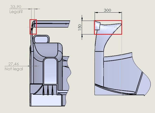
2) A variation of the rear wing height (the lower 300mm of the rear wing support are telescopic ;) ) of +/- 100mm gives a CoP difference of +/-40mm (also drag changes: to lower the rear wing is about the same as reducing the angle of attack and frontal section)

3) The front wing could be divided into two airfoil sections (not in the present CFD cad model, because it would cause a small additional resistence)

Numbers of point 1 and 2 have been estimated with the 2017 car (when I worked on the physics of the AssettoCorsa dynamic model that Gary is preparing).

Anyway: it would be fantastic to consider these realistic details and tuning, but they would be coupled with other simulation features, especially about mass distribution and inertia (ex. frontal heat exchangers).

User avatar
machin
162
Joined: 25 Nov 2008, 14:45

Re: [MVRC] Mantium Virtual Racecar Challenge 2018

Post

Interesting... 👍
COMPETITION CAR ENGINEERING -Home of VIRTUAL STOPWATCH

User avatar
CAEdevice
48
Joined: 09 Jan 2014, 15:33
Location: Erba, Italy

Re: [MVRC] Mantium Virtual Racecar Challenge 2018

Post

machin wrote:
24 Aug 2018, 21:18
Interesting... 👍
Ah... I forgot the rear suspension covers: they are 100% wings with my layout and give an opportunity to change the balance. The problem is that they have important effects on the cooling, much more than rear and front wings: you can see similar (but smaller) profiles mounted on F1 cars (ex. Ferrari) when running on low tracks with high temperatures.

... most of the secrets of my car has been revealed now :)