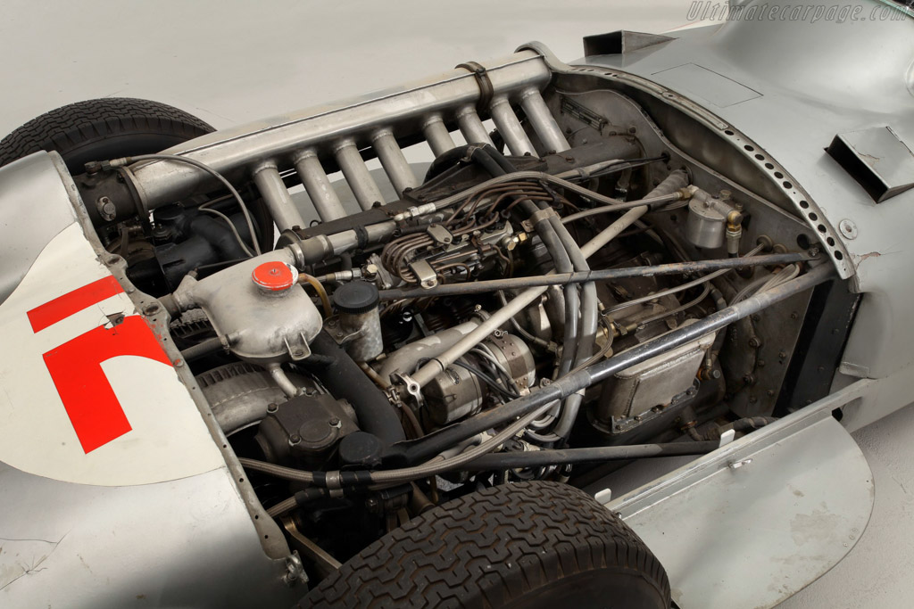
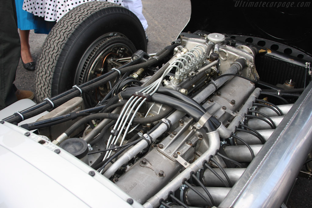
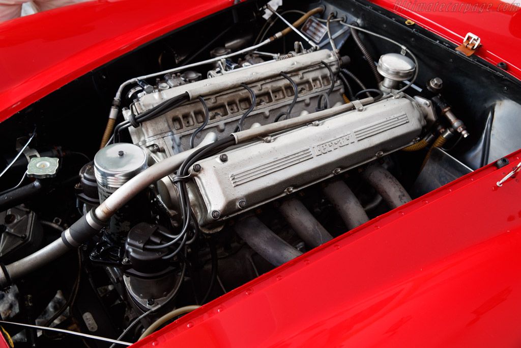
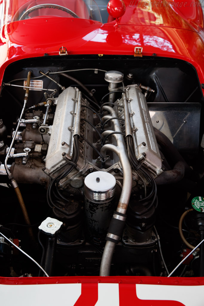
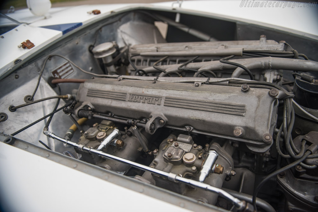
1955 Mercedes-Benz M196 2.5-litre eight
1955 Mercedes-Benz M196 2.5-litre eight: In 1952 50 year old Hans Gassmann was made responsible for racing car design department set-up to create the engine that Mercedes would use in its GP car for the 1954 2-1/2-litre formula. That engine was the M196, a straight eight inclined in the chassis with a drive take-off geared from center of crankshaft, this central gear train also drove the camshafts and engine accessories including injection pump, dual magnetos and water pump + oil pumps.
Historic sketches prepared by Gassmann showed 2 cam lobes controlling each valve, 1 lobe opened it the other a ‘D’ shaped lobe working through an ‘L’-shaped rocker pulled it closed again. Gassmann had revisited the desmodromic valve gear which both Dalage and Th.
Schneider had raced with in 1914 French GP. Because the desmodroic valve system could handle much larger and heavier valves a 2-valve combustion chamber was decided upon.
Forged-steel integral cylinders and heads were used, welded to 1-1.5mm sheet steel water jackets to form 2 4-cylinder blocks, no valve seat inserts were needed in a forged-steel head. Inlet valves with a 10mm stem inclined at 43 degrees angle from vertical and exhaust with a 12mm stem at 45 degrees.
Downdraught inlet porting through top of cylinder head and engine inclined at 37 degrees to horizontal. 14mm Bosch plugs were used. Injector positioned on cylinder wall just below the inlet valve with nozzle angled upwards 12.5 degrees. Fuel flow began 30 degrees ATDC on inlet stroke and continued for 160 degrees.
Mahle forged aluminum-alloy fully skirted pistons, the spacing of top 2 compression rings was wide so that hot gasses do not push their way down past both rings through the injector hole in cylinder wall, 2 additional plain rings above and below the gudgeon pin profiled on their lower faces to act as oil scraper rings.
Hirth built-up all roller bearing crankshaft, sections being held together by differential screw inside each bearing journal. Smaller main bearing journals than big end.
Silumin crankcase with main bearing covers at both ends. The rear cover also had a steady bearing for the output shaft driven from crank center gear. Castrol R was handled by 4 oil pumps, a scavenge pump outside the sump recirculated all the oil every minute at 8000RPM.
Specifications:
Cylinders l8.
Bore 76mm.
Stroke 68.8mm.
Stroke/bore ratio 0.91:1.
Capacity 2496cc.
Compression ratio 12.5:1.
Con-rod length 137.5mm.
Rod/crank radius ratio 4:1.
Main bearing journal 41mm.
Rod journal 55mm.
Inlet valve 50mm with 10mm stem and 12mm lift.
Exhaust valve 43mm with 12mm stem and 13mm lift.
Inlet opens 20 degrees BTDC.
Inlet closes 56 degrees ABDC.
Exhaust opens 50 degrees BBDC.
Exhaust closes 14 degrees ATDC.
In-cylinder direct injection.
Injector nozzle position on cylinder wall below inlet valve, angled upwards 12.5 degrees.
Fuel flow starts 30 degrees ATDC inlet stroke.
Fuel flow duration 160 degrees.
Peak power 290BHP@8500RPM.
Peak torque 248Nm@6300RPM.
Peak BMEP 182psi.
116.2BHP/litre.
0.71kg/BHP.
Piston speed corrected 20.2m/s.
0.71kg/BHP. Engine weight 205kg.
- Login or Register
No account yet? Sign up


