Two Element, Airfoil Grubbing

Breaking news, useful data or technical highlights or vehicles that are not meant to race. You can post commercial vehicle news or developments here.
Please post topics on racing variants in "other racing categories".
GIGAPUNK
GIGAPUNK
0
Joined: 13 Apr 2010, 22:00

Two Element, Airfoil Grubbing

Post

Howdy All,

I've recently started autocross racing where my car rarely encounters speeds over 80 mph. I have a long history of wing construction with r/c gliders, have read "Race Car Aerodynamics: Designing for Speed" by Joseph Katz cover to cover 3 times at least. And am interested in building my own rear ring for my SCCA Super Street Modified 300hp mazda miata autocross car. I am limited to 8 sq. ft., two elements and 200 sq. in. end plates. For other classes I should limit my span length to 5.5 ft. which if I'm to stay within the 8 sq. ft. total means that the combined width of the two air foils should be below 17.5".

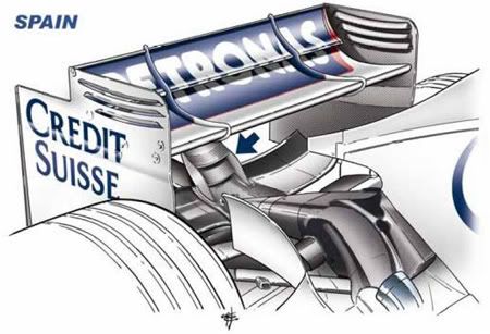
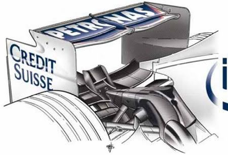
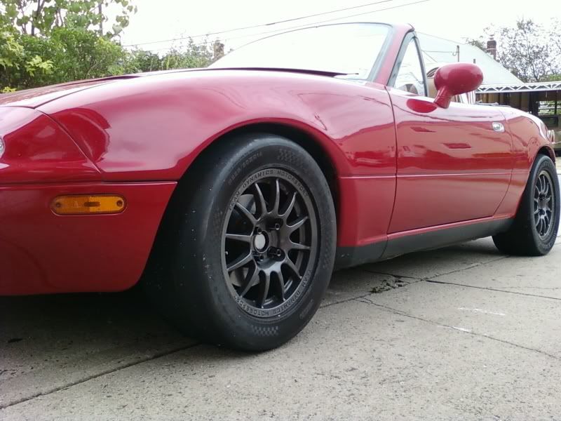
The car as it sits now.
Image

I found a company in Texas that will cut custom foam cores for the wings for a very modest fee.

http://www.flyingfoam.com/launch.html

However they require that:

"Airfoil Selection (from their website):
We have several hundred airfoil profiles to choose from. We also can generate NACA 4, 5, and 6 digit airfoils. We can cut any airfoil that has been designed or modified in Compufoil, Profili, or stored in Compufoil (.cor) file format."

I've been searching for help in selecting a pair of profiles for my two element wing. I'm a medical doctor, though and not an engineer. Thus the grubbing. I'm really hoping that somebody will just give me a solid airfoil reccomendation that will fit flyingfoam.com's requirements, so that I can build it.

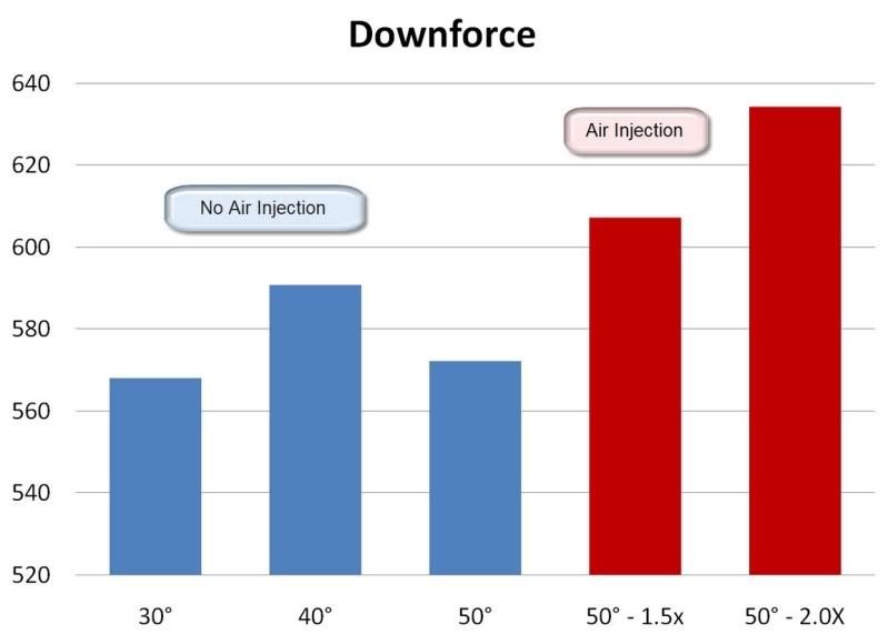
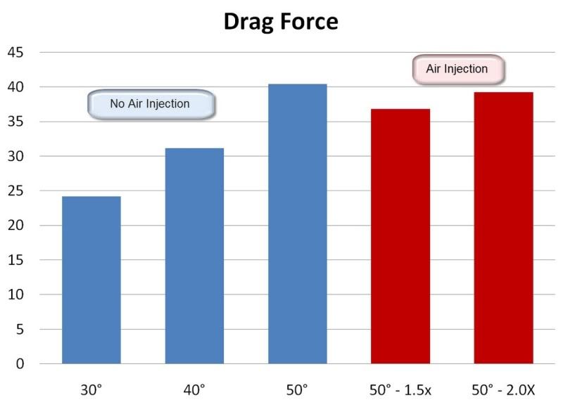
The car is a bit overpowered, so drag is not really a concern, just as big of a -cL as I can get get within the above constraints. I've seen so many great technical discussion on this forum, and I reall don't know where else to turn. Thanx a million guys.
Last edited by GIGAPUNK on 14 Apr 2010, 04:19, edited 2 times in total.

GIGAPUNK
GIGAPUNK
0
Joined: 13 Apr 2010, 22:00

Re: Two Element, Airfoil Grubbing

Post

I found the Benzing profiles.

http://www.benzing.it/enrico.profili.htm

But I still don't understand how I would figure out how big to space the two airfoils relative to each other, or how to split up my max allowable chord length between the two airfoils considering that they both have to be the same span. Should the primary use up 50% of my available surface area? 65%? 79%?...

GIGAPUNK
GIGAPUNK
0
Joined: 13 Apr 2010, 22:00

Re: Two Element, Airfoil Grubbing

Post

Found a sweet NACA article on pressure distributions for airfoils with external-airfoil flaps.

http://naca.central.cranfield.ac.uk/rep ... rt-614.pdf

Seems cL just kept increasing as the angle between the primary and flap increased from zero to 30 degrees. 40 degrees was also tested, but I don't understand the results completely.

Mystery Steve
Mystery Steve
3
Joined: 25 Sep 2009, 07:04
Location: Cincinnati, OH, USA

Re: Two Element, Airfoil Grubbing

Post

You're limiting your chord length to 5.5 ft? :wtf: Do you mean span?

Also, I assume you are just adding a rear wing? If so, you want to be careful with the mindset of "adding as much downforce as possible." While downforce does help with traction and cornering ability, you need to be mindful of the balance between the front and the rear.

Not to say you're wrong to add a wing, but it should be considered if the goal is to decrease lap times. However, if you just do this as a casual hobby and you want to build the wing for fun, then have at it...

GIGAPUNK
GIGAPUNK
0
Joined: 13 Apr 2010, 22:00

Re: Two Element, Airfoil Grubbing

Post

Mystery Steve wrote:You're limiting your chord length to 5.5 ft? :wtf: Do you mean span?

Also, I assume you are just adding a rear wing? If so, you want to be careful with the mindset of "adding as much downforce as possible." While downforce does help with traction and cornering ability, you need to be mindful of the balance between the front and the rear.

Not to say you're wrong to add a wing, but it should be considered if the goal is to decrease lap times. However, if you just do this as a casual hobby and you want to build the wing for fun, then have at it...
Doh! Yes I did mean span.
Many guys in my class with similar set ups are already pulling their rear sway bars completely. I'm already pretty loose, but don't want to pull the rear sway bar. If the wing tightens the car up too much I'll either shorten the rear sway bar arm length or add a front air dam/splitter.

I'm very mindful of balance, and am this all about fun.


slimjim8201 posted these on twin element wing that was originally published in racecar engineering, in the 'Reducing the drag of a two element wing through stall' thread:
Image
Image
Image

40 degrees is lookin pretty good
Last edited by GIGAPUNK on 14 Apr 2010, 04:23, edited 2 times in total.

Jersey Tom
Jersey Tom
166
Joined: 29 May 2006, 20:49
Location: Huntersville, NC

Re: Two Element, Airfoil Grubbing

Post

Racecar Engineering Magazine is 'meh' at best.

Personally, I would

(a) Put something flat/smooth on the bottom of the car
(b) Add a reasonably sized front splitter, whatever you can get away with
(c) Add substantial front roll stiffness with spring
(d) Slam front ride height
(e) Have a wide spread of rear spring/bar options
(f) Cut 3 rear wings of various configurations (low, medium, high DF)
(g) Test until you find the quickest combination

Edit - Actually.. is that a convertible???
Grip is a four letter word. All opinions are my own and not those of current or previous employers.

Mystery Steve
Mystery Steve
3
Joined: 25 Sep 2009, 07:04
Location: Cincinnati, OH, USA

Re: Two Element, Airfoil Grubbing

Post

I'd be careful utilizing those figures. They were developed for a specific wing setup, and don't necessarily translate to a different configuration. The problem with answering the big picture question you're asking is that there isn't necessarily a correct answer. A robust analysis of the combination of vehicle dynamics and aerodynamics, with respect to race car performance, requires a systematic approach. In other words, they are inter-related and should be treated as such. In some cases, reducing the drag at the expense of downforce can decrease lap times. See Monza vs. Monaco aero setups in F1...

For your purposes, I wouldn't bother getting too in-depth with the analysis. If you want to get into analysis of vehicle dynamics, you should really either develop an involved analysis or make a few "paper napkin calculations" and just test. It usually doesn't do much to go half way with the math. All you really need is a wing that has a wide range of adjustments so that you can trim the handling to your preferences. As JT said, I'd make a variety of wing profiles and assemble them so you can make a reasonable range of adjustment on the "flap" or second wing profile. Then go drive the thing... :D

Tom's suggestions are very good... from an aerodynamic standpoint, point "a" should be considered. You can definitely decrease drag and increase downforce by smoothing out the bottom. Some sheet metal and fasteners make that an "easy" job, assuming you have some experience working with sheet metal.

GIGAPUNK
GIGAPUNK
0
Joined: 13 Apr 2010, 22:00

Re: Two Element, Airfoil Grubbing

Post

Mystery Steve wrote:I'd be careful utilizing those figures. They were developed for a specific wing setup, and don't necessarily translate to a different configuration. The problem with answering the big picture question you're asking is that there isn't necessarily a correct answer. A robust analysis of the combination of vehicle dynamics and aerodynamics, with respect to race car performance, requires a systematic approach. In other words, they are inter-related and should be treated as such. In some cases, reducing the drag at the expense of downforce can decrease lap times. See Monza vs. Monaco aero setups in F1...

For your purposes, I wouldn't bother getting too in-depth with the analysis. If you want to get into analysis of vehicle dynamics, you should really either develop an involved analysis or make a few "paper napkin calculations" and just test. It usually doesn't do much to go half way with the math. All you really need is a wing that has a wide range of adjustments so that you can trim the handling to your preferences. As JT said, I'd make a variety of wing profiles and assemble them so you can make a reasonable range of adjustment on the "flap" or second wing profile. Then go drive the thing... :D

Tom's suggestions are very good... from an aerodynamic standpoint, point "a" should be considered. You can definitely decrease drag and increase downforce by smoothing out the bottom. Some sheet metal and fasteners make that an "easy" job, assuming you have some experience working with sheet metal.
I'll definitley check the rule book to see if I can add some type of undertray.

Are there any wings that have a wide range of adjustments that you could reccomend?

I got an e-mail from Bob at FlyingFoam.com. But he didn't know of any airfoils that were specifically designed specifically for two elements.

"For low speed, high lift, look at the E423, S1223, S1210 and the Liebeck airfoil. You might be able to Google the Libeck. The others are on the UIUC web site. I have a link to it on our links page."

marcush.
marcush.
159
Joined: 09 Mar 2004, 16:55

Re: Two Element, Airfoil Grubbing

Post

the undertray thing is in theory something but reality is not really backing this up,if your are not doing it properly.And an undefloor is quite a task to undertake.

not to mention the implications of engine bay ventilation...the miata surely vents through the bottom..so closing this will help the drag,but you need a new path for the hot air going out in a convenient place.

GIGAPUNK
GIGAPUNK
0
Joined: 13 Apr 2010, 22:00

Re: Two Element, Airfoil Grubbing

Post

My uncle is a composites expert, and I'm going to be able to get some of his help next month, so I really need to get these foam cores ordered so that he can help me cover them in CF. I may just pick two of the Benzing profiles, but I don't know how to split up my 17.5" of available chord between the primary and flap. IN F1 they seem to vary from a 80/20 split all the way to a 30/70 split like in the bottom pic. Where should mine be?!

Image

Image

GIGAPUNK
GIGAPUNK
0
Joined: 13 Apr 2010, 22:00

Re: Two Element, Airfoil Grubbing

Post

I was looking up the profiles that Bob suggested and calculating out my likely reynolds numbers. That S1223 is might work.

Image

With a primary chrod using 67% of my available width I'd be looking at reynolds numbers of

22mph 3x10^5
67mph 9x10^5

These airfoils below look very promising. Originally designed for remote control glider competitions where reynolds numbers > 2 x 10^5 are generally targeted.

UIUC Airfoil Coordinates Database (Reference)
Last update 12/15/95

S1210 (11.87%) and S1223 (11.93%) for R/C Heavy Lift / Slow Flight Competition

The S1210 was designed for the SAE R/C airplane heavy-lift competition. In wind tunnel tests, the S1210 airfoil achieved 15% more lift than the FX 63-137, which to date has been one of the favorites for the competition. The S1223, used in the UIUC Low Speed Airfoil Tests logo, is the next in the series and is predicted to have 30% more lift than the FX 63-137. These airfoils are not expected to perform well much below a Reynolds number of 200,000 - the typical design Reynolds number for the competition. These airfoils will likely find their way into other R/C aircraft heavy-lift competitions appearing across the country.

User avatar
machin
162
Joined: 25 Nov 2008, 14:45

Re: Two Element, Airfoil Grubbing

Post

The book "Competition Car Downforce" (by Simon McBeath) has some wing data in its final few pages... In its dual element example both elements are NACA23012 profile, and the chord of the flap is 25% of the main plane. Its not obvious what the gap is between the two, but it looks very small, somewhere in the region of 2 to 3% of the main plane's chord.

With the flap set to 20 degrees (compared to the main plane), and an overall angle of attack of the two elements of 12 degrees (i.e. measure the line from the leading edge of the main plane to the trailing edge of the flap and compare it to horizontal) it has a Cl of 2.35, this reduces to 1.5 when the overall angle of attack reduces to 4 degrees (keeping the angle of the flap compared to the main plane at 20 degrees).

This guy knows his stuff; he build wings for a living, writes regularly for Racecar Engineering, and seemed a pretty nice guy when I had lunch with him a few years back at Gurston Hillclimb school (Similar to your Autocrossing).
COMPETITION CAR ENGINEERING -Home of VIRTUAL STOPWATCH

User avatar
machin
162
Joined: 25 Nov 2008, 14:45

Re: Two Element, Airfoil Grubbing

Post

Oh, and the leading edge of the flap overlaps the trailing edge of the main plane by about 3% of the chord of the main plane....
COMPETITION CAR ENGINEERING -Home of VIRTUAL STOPWATCH

GIGAPUNK
GIGAPUNK
0
Joined: 13 Apr 2010, 22:00

Re: Two Element, Airfoil Grubbing

Post

Thanks for the specific response. I found some interesting studies that were done for solid wing sail boats and they were using the same symmetrical profiles, and the same 2-3% spacing between the flap and primary as well.

I thought this was interesting,

http://www.tspeer.com/Wingmasts/airfoils.html

"The NACA 0012 provides a good section for the flap because of its front loading, which allows the whole flap to be used for the airfoil's pressure recovery. Any tendency of the flap to form a leading edge pressure peak can be suppressed by adjusting the slot gap... The NACA tested the 23012 airfoil with a 23012 airfoil as a 20% chord flap, and the data are compared here with the computational method. The GA30-612 with a GA37-315 flap is used on some popular ultralights,"

Image

GIGAPUNK
GIGAPUNK
0
Joined: 13 Apr 2010, 22:00

Re: Two Element, Airfoil Grubbing

Post

Bob Mellen (bob@flyingfoam.com) told me that it would cost $25 per airfoil to digitize a .jpeg for his foam cutters. It's looking like I might just order this up. The primary is at 10 degrees in this image. The flap is at 45 degrees to the primary and its chord is 25% of the primary. The gap between the two is 2.5% of the primary's chord. The primary airfoil was taken from images of a recent F1 wing section, and the flap was taken from an image that was originally published in 'Race Car Engineering'.

Image

This is the configuration I am planning on ordering and testing initially. If anyone has any suggestion I'm very open to them, as this is a bit of a shot in the dark.