Scarbs T-Tray proposal

Here are our CFD links and discussions about aerodynamics, suspension, driver safety and tyres. Please stick to F1 on this forum.
hardingfv32
hardingfv32
35
Joined: 03 Apr 2011, 19:42

Re: Scarbs T-Tray proposal

Post

"Specifically a team requesting clarification if a see-saw set up would be legal, its was clarified it would be in contravention of the"

This statement means nothing. We have no idea what the drawing of the see saw method was presented. Some of the illustrations presented have shown a clear amount of shifting/shearing between the rear of the splitter structure and the front of the chassis/tube. This is clearly not the case with RB, as the splitter is part of the floor assembly.

Know I am not saying that the floor can't be designed to flex downward at this point, but it goes get back to the issue of how much flex is acceptable from an actual measurable application. We know that all the floor structure flex if they hit a big enough track irregularity.

Brian

Richard
Richard
Moderator
Joined: 15 Apr 2009, 14:41
Location: UK

Re: Scarbs T-Tray proposal

Post

Is this chasing shadows? Does the see-saw method actually exist?

The only way to test for this is to completely change the rig and support the cars on the jacking points. Then they'll be able to test the entire system rather than individual components as they do know.

The key will be to introduce that test without accidentally imposing a requirement for cars to be significantly stiffer hence a redesign of all cars. We saw with the so called stricter front wing tests last year that they simply allowed double deflection for double load and everyone carried on as normal.
Last edited by Richard on 17 Oct 2011, 18:15, edited 1 time in total.

User avatar
atanatizante
115
Joined: 10 Mar 2011, 15:33

Re: Scarbs T-Tray proposal

Post

atanatizante wrote:Does anybody noticed the secondary or maybe can we say the primary effect of this flexible splitter/tea tray? What happens with the opposite side of the splitter/tea tray which is not hitting the ground? It applies an upside force to the plank hence making some DF to the car, don`t you think? And if this force is applied near or at the same level/plane of the CoG the better ...
I draw an intuitive sketch in order to explain my hypothesis:
Therefore tea tray is made up by 2 independent elements which are united at the same pivot where Scarbs was position it. The whole mechanism is concealed in a carbon fiber shell. So in the race this situation occurs:
Image
FIA test does`t hurt the structure either …
"I don`t have all the answers. Try Google!"
Jesus

hardingfv32
hardingfv32
35
Joined: 03 Apr 2011, 19:42

Re: Scarbs T-Tray proposal

Post

If it does.... they only reasonable explanation of its use made so far in this thread is that the "see saw" system allows the car to run closer to the ground without causing excess wear to the plank. This is a valid point that we can not evaluate without more knowledge of plank wear characteristics.

Ringo

The first section of plank must be 1000mm long. This would put it 250mm beyond the two large wear test holes located at 750mm. These holes are easy to spot on the RB Monza photo.

The plank is only 10mm thick and the mounting hardware locations are not specified. So the first section of plank would not have to be mounted beyond the end of the splitter (say 750mm back). This would not seem to be the case with the RB at Monza, as there seems very little wear beyond the 750mm wear holes.

I am not sure how much force it would take to bow a 10mm plank. If we decide on some mounting point locations (fulcrum points for a test) I could run a test on a piece of plywood.

Brian

User avatar
ringo
230
Joined: 29 Mar 2009, 10:57

Re: Scarbs T-Tray proposal

Post

Image

Image

I am not not seeing any mechanism here. I am seeing a rigid 1 piece carbon floor.
Which is mated to a rigid plank held down by high strenght bolts.

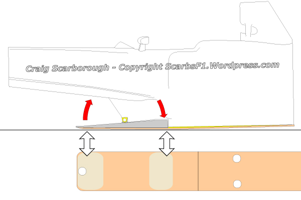
There is no pivot. It's a cantilever.

Also one error in this diagram is that it doesn't take into account the whole body of the car.
That pivot cannot be assumed to be stationary. The real pivot would be the rear wheel center line.
This point will only act as a pivot if the forces on the front axle are greater than the force acting at the tip of the splitter.
All moments acting on the car taken about the rear wheel center line are to be greater than the clokwise moment required to bend the 1 piece CFRP about that pivot point.
So if we know how much force it takes a 1 piece floor bonded to the plank by the suspected deflection point and we compare to the total force on the car we can know if the idea feasible.

In leymans terms if i nail a metal ruler to a table i have to include the weight of the table and use the table's rear legs as the pivot point, not the nail.
Only if the weight of the table is far greater than the force to have deflection in the ruler do i ignore it, as it wont have any significant motion compared to the ruler.

If the ruler is so stiff that the moment applied to it surpasses the moment of the table's weight about the rear legs, the table will lift before we see any deflection in the ruler about the nail (the nail being the other pivot point).

So the deflection force at the splitter, and thus the strength of the cfrp and plank have to be really small compared to the other external forces on the car.

Numbers have to come into play to analyse this idea. It may not be statically determinate either.

So are the aero loads and their moments stronger than that moment at the splitter?
For Sure!!

imightbewrong
imightbewrong
17
Joined: 07 Aug 2008, 16:18

Re: Scarbs T-Tray proposal

Post

from scarbs blog, from Monaco this year:
Image

hardingfv32
hardingfv32
35
Joined: 03 Apr 2011, 19:42

Re: Scarbs T-Tray proposal

Post

I think the assumption is that the floor/splitter assembly (disregarding the plank for the moment) pivots around the leading edge of the tub/chassis. This is reasonable, as we can assume the tub is many times stiffer than the floor assembly. In the case of RB, it would seem that the pivot is a vertical blade structure. How the floor attaches to this blade would tell us a lot about RB efforts to you a "see saw" system. Spreading the loads from the narrow blade across the width of the splitter would be challenging.

The illustration above indicates an actual hinge which would not be necessary or legal. All that is needed is a flexure at this location which puts you into that wonderfully grey area of flex and you have your way around the rule restrictions.

Maybe the real purpose of the square ducts on the sides of the splitter is to prevent it from bending over the pivot point/blade?

The seam in the plank as shown above would be located after the inspection holes. I would say the scale of the plank does not match the "see saw" illustration.

Brian
Last edited by hardingfv32 on 17 Oct 2011, 21:26, edited 1 time in total.

xpensive
xpensive
214
Joined: 22 Nov 2008, 18:06
Location: Somewhere in Scandinavia

Re: Scarbs T-Tray proposal

Post

ringo wrote: ...
Also one error in this diagram is that it doesn't take into account the whole body of the car.
That pivot cannot be assumed to be stationary. The real pivot would be the rear wheel center line.
This point will only act as a pivot if the forces on the front axle are greater than the force acting at the tip of the splitter.
All moments acting on the car taken about the rear wheel center line are to be greater than the clokwise moment required to bend the 1 piece CFRP about that pivot point.
So if we know how much force it takes a 1 piece floor bonded to the plank by the suspected deflection point and we compare to the total force on the car we can know if the idea feasible.
...
I've read your attempt at an analysis a few times now and I have to admit failing to grasp anything of it, zip, nada.

I have no problems with isolating the sew-saw in its cradle mechanically-wise, though I doubt it for stability reasons, is it obvious that aerodynamic forces will keep it in horizontal position until it touches ground and what will the contact-force be?
"I spent most of my money on wine and women...I wasted the rest"

User avatar
ringo
230
Joined: 29 Mar 2009, 10:57

Re: Scarbs T-Tray proposal

Post

heh heh, i guess i need a diagram for you to see it.

Ok xpensive.

When you put a lug tool on a wheel to romove a lug.

What must happen for the lug to rotate and not the wheel?

That's the summary of what i wrote.

You can't isolate the lug by itself and your moment arm on the lug tool and then not account for the axis of rotation of the wheel and the inertia of the wheel.

Likewise the other forces on the car and their moments about a point.
For Sure!!

marcush.
marcush.
159
Joined: 09 Mar 2004, 16:55

Re: Scarbs T-Tray proposal

Post

the plank itself is not very stiff its 10mm birch plywood after all it is easily bend a few mm over a length of 1000mm.The fixation of the plank to the undertray will play a major part in the stiffness(eg can the plank move /slide when the teatray is bending pivoting )wear can only be controlled when fastening points are doubling up as wear points ,as the wood will wear away like molten butter...

User avatar
pocketmoon
0
Joined: 17 Oct 2011, 23:14

Re: Scarbs T-Tray proposal

Post

The t-tray is beautifully sculpted ;) I wonder if the design itself (without a pivot) would allow for extra deflection at the front when the whole unit is not held flat on the ground by the weight of the car, i.e. when raised, as the front section deflects up, the curved shape (and subtle notching) forces the rear to bend out/down (which they could not do when held flat on the floor)

:?:

User avatar
ringo
230
Joined: 29 Mar 2009, 10:57

Re: Scarbs T-Tray proposal

Post

@ marcush it's not only bending either.
It's under a tensile load. Since the plank is fixed to the front of the splitter as well. So there will be some stretching of the plank to force it to increase in length.
Also the splitter is one piece with the floor and it's crossection is 50mm or more in height. It has considerable bending strenght.
For Sure!!

hardingfv32
hardingfv32
35
Joined: 03 Apr 2011, 19:42

Re: Scarbs T-Tray proposal

Post

The photo (RB floor) above maybe adds a few more clues.

1) We asked what the large hole was about at the front of the floor at the time and figured it was to get the ballast lower. This is exactly where the rear section of the splitter needs to move downward to make the "see saw" system viable. With this hole in the floor, only the plank needs to bend and no part of the floor.

2) How is the plank mounted? You can see six evenly spaced holes along the center floor area, but they are not on the lowest level/plain of the floor where the plank would be in contact. There also does not seem to be pairs of holes where you might expect a seem, so maybe the RB plank is one piece.

3) The plank mounting system only has an surface area restriction. The front mounting system could allow some motion of the plank relative to the mounts/floor.

Brian

xpensive
xpensive
214
Joined: 22 Nov 2008, 18:06
Location: Somewhere in Scandinavia

Re: Scarbs T-Tray proposal

Post

ringo wrote: ...
You can't isolate the lug by itself and your moment arm on the lug tool and then not account for the axis of rotation of the wheel and the inertia of the wheel.
...
However well intended, this analogy is out of context, the wheel-centers have nothing to to with the see-saw connected to the chassis. This is to my mind just as relevant as claiming you can harness thermal xpansion by referring to Poisson's ratio.

This forum would benefit from a technical moderator me thinks.

@marcush; I seem to remember the plank being 10 mm thick MDF or something like it, but I agree, it will create a sandwich of sorts if fixed to the splitter.
"I spent most of my money on wine and women...I wasted the rest"

User avatar
ringo
230
Joined: 29 Mar 2009, 10:57

Re: Scarbs T-Tray proposal

Post

You still don't see the big picture do you?

Never mind then. Back to the imagineering.
For Sure!!